「既往知見」の版間の差分
Ohgi Hiroshi (トーク | 投稿記録) |
Ohgi Hiroshi (トーク | 投稿記録) |
||
| 82行目: | 82行目: | ||
=====燃料集合体部材の溶融===== | =====燃料集合体部材の溶融===== | ||
(2) Liquefaction of fuel assembly components for BWR (stainless steel (SS) / B4C / Zr) | (2) Liquefaction of fuel assembly components for BWR (stainless steel (SS) / B4C / Zr) | ||
| 125行目: | 125行目: | ||
倉田コメント: | <span style="color: red;">倉田コメント: | ||
(ここに、Hofamannの温度上昇にともなう、材料の反応メカニズムの図を引用し、その要素反応を概説する) | (ここに、Hofamannの温度上昇にともなう、材料の反応メカニズムの図を引用し、その要素反応を概説する) | ||
2020年12月7日 (月) 18:33時点における版
過去の原子力施設での事故事例
スリーマイルアイランド島(TMI-2)原子力発電所事故
チェルノブイリ原子力発電所事故
模擬試験、ウランの特性に関する既往文献等
燃料・構造物の溶融及び凝固挙動
シビアアクシデント時の燃料、構造物の溶融及び凝固挙動 図表番号は仮のものを挿入
炉心での燃料溶融
燃料ペレット-ジルカロイ被覆管界面の液相化進展挙動

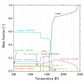
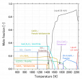
ここでは、燃料ペレットとジルカロイ被覆管界面の反応について概説する。事故時、炉心の冷却能力が失われることで、崩壊熱により燃料の温度が徐々に上昇する。それに伴い燃料ペレット(UO2)とジルカロイ被覆管(Zry)が反応し、溶融にいたる。燃料溶融挙動は温度ごとにいくつかの支配的な化学反応プロセスが存在する[1]。以下で、それを説明する。(図x1:参照)
通常運転時
通常運転時では、被覆管温度はおよそ300℃となる[2]。冷却水に接触しているZry表面にZrO2膜が形成され、その厚さは、炉型や照射期間によるが、20 μm程度となる[2]。この膜は不働態として働くため、通常運転時にはα-Zr(O)相はほとんど形成されないと考えられている。 仮の参考文献。H10版のみ手元にあり、P278にそれっぽい記述。最新版はH25。他に探したほうがいいかも。倉田コメント:原子力学会編:軽水炉燃料のふるまい、あたりに記載があると思います。適当な記述がなければ、平井さんに相談してみてください。
酸素の拡散が支配的な温度範囲(約1800℃以下)
炉心への冷却水の供給が不足すると、冷却水の水位が低下し、炉心・燃料が水蒸気中に漏出する。これにより、燃料温度が上昇する。燃料温度の上昇にともなって起こりうる化学反応については、別途記述する(Hofmannの図にリンク)。UO2とZry界面では、比較的低い温度(約1800℃以下)では酸素の拡散が支配的と考えられている[3]。UとZrの拡散は界面近傍に限定され、そこで、液相(U-Zr-Oメルト相)を含む薄い反応層が形成される。その先に燃料からZryへの酸素拡散によるα-Zr(O)相が形成される。被覆管外周部では、水蒸気酸化(水蒸気/Zr反応)により、ZrO2層が成長し、さらに内側にα-Zr(O)層が形成される。また、被覆管の中央にはβ相が残留する。約1200℃を超えると、水蒸気/Zry反応が急速に進み、温度の急上昇が起こる(毎秒8℃以上)[2]。
- 水蒸気/Zr反応: Zr + 2H2O → ZrO2 + 2H2 (ΔH=-586 kJ/mol)
参考文献:Hofmann論文 たぶんこれ
液相化が急速に進展する温度温度(約1800℃~2200℃)
約1800~2200℃の範囲では、複雑な反応が起こるが、全体的な傾向としては、急速にU-Zr-Oメルト相が拡大する。熱力学的には、約1950℃で残留しているβ相(酸素固溶飽和)はほとんど液相化する。約2100℃ではα-Zr(O)相も溶融する。これらはU-Zr-Oメルト相と一体化すると考えられる。U-Zr-Oメルト相は、内側に残留するUO2と外側に残留するZrO2を溶融して成長するが、温度によってそれらの溶解度に制限がある[1]。約2200℃までには、UO2/U-Zr-Oメルト/ZrO2の構造が形成されると考えられている[1]。
溶融した燃料の下方へのリロケーション(約2200℃以上)
Phebus-FPT試験[4]等の模擬試験での観測結果に基づき、約2200℃でU-Zr-Oメルトが燃料棒の外周から噴出し、炉心下方向にリロケーション開始すると考えられている[1]。シビアアクシデント解析コード(MAAP、MELCOR、ASTEC、SAMPSONなど)では、この温度が燃料溶融温度としてモデル化されている。また、ASTECコード等では、溶融物がZrO2膜を破って下方にリロケーションするか、あるいは、ZrO2膜の内側に維持されたまま、機械的に崩落するかについて、閾条件があるとされている。約2200℃に到達した際の外周のZrO2膜が約200~250μmより厚い場合、U-Zr-Oメルトはこれを破ることができず、燃料棒内部で保持され、なんらかの衝撃により、機械的に崩落すると考えられている。
参考文献:Phebusの論文。これ?PFT 0 - 5全部ある or 持ってる人いる?
燃料溶融進展にともなう溶融物の平均組成の変化
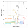
In SA-analysis codes, a so-called ‘eutectic’ liquefaction model between α-Zr(O) and UO2 is generally implemented. However, this model is a sort of simplified model specified for the SA-analysis and hence this model could not precisely describe the liquefaction mechanism of the fuel rod. Essentially, the liquefaction progression of the fuel rod in the early phase can be recognized using the U-Zr-O ternary phase diagram [8]. Figure 2 schematically indicates the variation in the local composition of the fuel rod with increasing temperature. In the normal operation, the average composition could be plotted in somewhere between UO2-Zr line (usually richer in Zr in BWR fuel) and then gradually sifted toward UO2-ZrO2 line by the oxidation of Zr-base alloy at the outer surface (A⇒B⇒C⇒D) as the accident progresses. This model indicates that the chemical reactions happening in the fuel rod in the early phase could be thermodynamically discussed based on the phase stability in the UO2-ZrO2-Zr ternary region. In this particular region, one needs the thermodynamic data of fluorite (FCC), face-centred tetragonal (TET), and monoclinic, HCP, BCC and liquid. The FCC, TET and monoclinic phases are essentially oxidic solid solutions and on the other hand the HCP and BCC phases are metallic solid solutions (alloys). A more complicated thermodynamic description is necessary for the liquid phase. At relatively low temperatures, the U-Zr-O melt is a dominant component for liquid (so-called ‘metallic’ melt). The composition range of the metallic melt is gradually expanding with increasing temperature. Then, at higher temperatures (above approximately 2550 °C), the metallic melt (U-Zr-O) and oxidic melt (UO2-ZrO2) could dissolve each other. This requires the complicated thermodynamic model for liquids in the U-Zr-O system. Also, a miscibility gap formed at the intermediate temperature region requires more complicated thermodynamic model. Nevertheless, the reasonable thermodynamic data are already stored in the current databases (TAF-ID and NUCLEA). However, the benchmark-1 (see chapter 4.2.3) pointed out that the thermodynamic functions for the FCC and TET phases implemented in TAF-ID and NUCLEA are slightly different from each other. This phase transition is certainly important when discussing the solidification path of the U-Zr-O melt under a slightly reducing condition (this could potentially happen in the FDNPS accident). Accumulation of experimental data for the UO2-ZrO2-Zr ternary region and the improvement of thermodynamic data is still necessary. Figure 17: Variation in the local composition of the fuel rod with increasing temperature. A’ represents the initial internal oxidation (-Zry formation) at the initial temperature excursion and A represents the onset of major oxidation/liquefaction reactions.
Step-1( ~1200℃):
燃料-被覆管での相互拡散反応が生じる。 平均組成は、UO2-Zry線(A点)に存在する。
Step-2(1200℃~2550℃):
被覆管外周部が酸化される。 その後、燃料崩落により水蒸気酸化(水蒸気/Zr反応)が収束し、燃料温度の低下する。
平均組成は、Zr-UO2-ZrO2三角形内に移動する(A点⇒B点⇒C点、燃料崩落により酸化が収束)。
C点まで酸化が進行したと仮定すると、温度の上昇に伴い、亜化学量論のU-Zr-Oメルトが形成される。(Zry / UO2の反応進展参照;リンクを貼る) その後、燃料崩落が起こり温度が低下することにより、UO2残渣、ZrO2残渣、U-Zr-Oメルトの凝固物が堆積する。
このように、崩落・堆積した炉心物質をルースデブリという。(TMI-2の場合、上部ルースデブリに相当する。(TMI-2該当ページのリンクを貼る))
Step-3(2550℃~ ):
図XXに示すように水蒸気流路が変化し、ルースデブリの外周にクラストが形成され、水蒸気流入が遮断される。
それに伴い、崩壊熱により、ルースデブリの温度が再上昇し、コリウムが形成される。
この過程で酸化が進行し、ほぼ二酸化物(oxidic corium)になる。
平均組成は、UO2-ZrO2上に存在する(TMI-2、VULCANOの解析結果より、コリウム凝固物の平均組成は、元のUO2:Zr比よりややZrリッチになる。;リンクを貼る)。
その後に、コリウムの下部プレナムへのリロケーションと再凝固・再溶融の話を書く
また、最近の検討例としてBWRドレナージシナリオのことを書く
平均組成の変化を示した図を貼る
- Example.jpg
キャプション1
燃料集合体部材の溶融
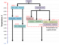
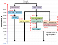
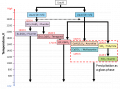
(2) Liquefaction of fuel assembly components for BWR (stainless steel (SS) / B4C / Zr) Figure 18(a) illustrates a horizontal cross section of a prototypic BWR fuel assembly, which is mainly consisted of fuel rod, control blade and channel box [9]. The fuel assembly is surrounded by a channel box made of Zr-base alloy. It should be noted in the case of BWR that the quantity of Zr is certainly larger than that of PWR (approximately twice in amount). Furthermore, an important feature is that the control blade is placed outside the channel box and away from the fuel rods. Figure 18(b) indicates the schematic image of the liquefaction progression of the control blade and channel box. Major components for the interaction are (1) a control rod made of B4C absorber material and stainless steel (SS-304) cladding, (2) a blade sheath made of SS-316 and (3) a Zry-4 channel box. Several dominant reactions occur with increasing temperature: (a) interaction between B4C and SS in a control blade, (b) oxidation of the outer surface of the channel box, (c) interaction between the B4C and SS melt and Zry-4 channel box, (d) steam oxidation of B4C-SS-Zr melt and remaining B4C. Consequently for the detailed understanding of the liquefaction progress of the BWR control blade and channel box, a comprehensive thermodynamic database for the Fe-Ni-Cr-Zr-B-C-O system is necessary. In the first step, reactions (a), (b), (c) and (d) could be evaluated based on several sub-systems.
Figure 18(a) Schematic image of a horizontal cross section of a prototypic BWR Fuel assembly. The red square shows the section illustrated in Fig. 18(b).
Figure 18(b): Schematic image of liquefaction progression at the interface between the control blade and the channel box.
Reaction (a) (B4C-SS system): So-called ‘eutectic’ melting between B4C and SS could occur at approximately 1200 °C. The Fe-B-C ternary phase diagram indicates that the most of SS cladding (major component: Fe) and a small amount of B4C are liquefied by the ‘eutectic’ formation. Hence, a significant amount of B4C is able to remain in the B4C-SS melt [10]. For more detailed understanding of the ‘eutectic’ melting, one needs to evaluate selective Fe-C reactions as opposed Fe-B reactions in the Fe-B-C melt and the local precipitation of Cr-boride [11, 12]. Table 16 shows the current assessed status of the ternary sub-systems of the B4C-SS systems. (‘⭕’ means the full assessment and ‘-’ means that its system has not been assessed yet.) The most important sub-system for this particular interaction is clearly Fe-B-C, because Fe is a dominant component of SS, which is already stored in both of TAF-ID and NUCLEA. Also, Fe-Ni-Cr system is already stored in the both databases. By using these databases, the ‘simplified’ evaluation of the ‘eutectic’ melting between B4C and SS could be carried out. However, the databases are still insufficient for the other subsystems especially including Cr, B and C. Cr could selectively react with B and C during solidification of the melt. This reaction appears to be important for the characterization of metallic debris [13]. Table 16: Current assessed status of ternary sub-systems regarding the liquefaction of the BWR control rod, which stored in TAF-ID and NUCLEA
Reaction (b) (Zr-O system):
As for the thermodynamic understanding of the oxidation of the channel box, one needs the Zr-O binary database which is already stored in the both databases.
Reaction (c) (B4C-SS-Zr-O system):
After the control blade melt (SS-B4C melt) makes contact with the Zry channel box, there is an interaction between the SS-B4C melt and the partially oxidized Zr. Several chemical reactions could simultaneously progress and hence the overall phenomena are very complicated. A kinetic model is definitely necessary for the detailed understanding. Thermodynamic database could identify the tendency (driving force) or threshold condition for the reaction.
The interaction’s progress depends on the thickness of the Zry surface oxide of the channel box. If the oxide film is not sufficiently protective in a non-oxidizing atmosphere, the interaction between SS-B4C melt and Zr can occur upon contact. As a result, B and C are transported to the Zry via liquid and could cause a sudden change of the system toward its equilibrium state, in which Zr-boride or Zr-carbide could precipitate in the melt. This is predicted to be an exothermic reaction.
Table 17 shows the ternary subsystems regarding the liquefaction between the non-oxidized Zircaloy channel box and the SS-B4C melt (in addition to Table 16). The dominant subsystem for this particular interaction could be Fe-Zr-X (X: Ni,Cr,B,C). The database is still insufficient for developing the mechanistic model. Also, considering the solidification path of the metallic debris, one needs to improve Zr-B-X and Zr-C-X databases.
Table 17: Current assessed status of ternary subsystems regarding the interaction between SS-B4C and non-oxidizing Zr (in addition to Table 16)
On the other hand, in the case of a thick oxide film on the Zry channel box. This interaction (SS-B4C and Zr) does not significantly occur and only SS-B4C melt relocates to the lower part (the channel box could maintain its original configuration during the absorber rod melting). Then, after melting of the Zr-channel box interior at higher temperatures, one needs to evaluate the dissolution of ZrO2 in the metallic melt which could be extremely important to the metallic debris characteristics.
Table 18 shows the ternary sub-systems with oxygen. Both databases can roughly evaluate the effects of oxidation. However, the formation of ternary compounds could not be sufficiently evaluated using these databases. Also, TAF-ID does not store any databases on the stable compounds of B-oxide in the melt.
Reaction (d) (B4C-SS-Zr-O system):
The steam oxidation of the SS-B4C-Zr melt is extremely important for the characteristics of the metallic debris. Also, the formation of B2O3 could accelerate the liquefaction of the fuel rod, because the melting temperature range of B2O3 is ~ 450-465 °C and it could allow the easy contact/wetting with the fuel rod. Moreover, volatilization of B is extremely accelerated by the steam oxidation and gaseous boron oxides could influence the chemical stability of volatile FP, such as Cs and I [10, 14-15]. The improvement of B-related database is highly recommended.
倉田コメント:
(ここに、Hofamannの温度上昇にともなう、材料の反応メカニズムの図を引用し、その要素反応を概説する)
その後に、BWRの1Fで重視すべき反応をまとめて述べる。
In-vessel debrisの凝固
倉田コメント:
In-vessel debrisの凝固説明文追記
二酸化物コリウムの凝固とU-Zr-Oの凝固が異なることの説明
In-Vessel debrisの凝固に関する熱力学解析 (凝固パス逆問題解析)
Case-1: 亜量論U-Zr-Oメルトからの凝固
最高到達温度 約1900℃~約2550℃ 説明文追記 〇〇組成の液相が 急冷:〇相と〇相が検出される可能性 徐冷:〇相と〇相が検出される可能性
- Example.jpg
キャプション1
- Example.jpg
キャプション2
Case-2:UO2-ZrO2コリウムからの凝固
最高到達温度 約2550℃~ 説明文追記 〇〇組成の液相が 急冷:〇相と〇相が検出される可能性 徐冷:〇相と〇相が検出される可能性
- Example.jpg
キャプション1
- Example.jpg
キャプション2
Case-3:金属メルトからの凝固(現在解析中)
3-1) SS-B4C 最高到達 〇〇組成の液相が 急冷:〇相と〇相が検出される可能性 徐冷:〇相と〇相が検出される可能性
3-2) SS-B4C-Zr 〇〇組成の液相が 急冷:〇相と〇相が検出される可能性 徐冷:〇相と〇相が検出される可能性
- 凝固パス逆問題解析
実デブリサンプル中に同定された相により、デブリ最高到達温度、冷却状態(徐冷、急冷)および組成を評価することができる。 参考リンク
Ex-vesselでのdebris溶融・凝固
事故時においてRPV下部プレナムにスランピングした燃料デブリが再溶融し、下部ヘッドを破損させた場合、RPVからペデスタルへ燃料デブリが移行する。1Fのペデスタル部では玄武岩系(シリカ系)コンクリートが使用されており、落下した溶融燃料とコンクリートの高温反応(Molten Core Concreate Interaction; MCCI)を起こすと想定されている。MCCIの進行に影響する因子としては、コンクリートの材質、移行してきた燃料デブリの組成(特に、平均的な酸化度や金属成分が含まれるかどうか)、デブリ温度(比較的温度の低いデブリが崩落する場合には、MCCIが進行しない可能性が考えられる(内部調査結果:2号機、3号機)リンク、3号機まだ)、また、デブリの特性には、冷却条件(徐冷or急冷)も影響する。
Ex-vessel debrisの凝固 に関する 熱力学解析
シリカ系コンクリートと溶融コリウムの間でMCCIが発生したと仮定し、熱力学計算ソフトThermo-calcを使用し、Ex-vessel debris凝固時の析出相の同定と成分偏析の解析を実施した。データベースはOECD/NEAの国際汎用熱力学データベースTAF-ID[5]を使用した。
シリカ系コンクリート、PWR条件でのコリウムのケース(CEA 模擬試験条件)
仏国CEAで行われた、シリカ系コンクリートとPWR条件を想定した模擬コリウムを用いたEx-vessel debrisの凝固試験[6]を参考に、凝固時の相析出挙動(凝固パス)の解析を実施した[7]。 本項目の論文は現在執筆中、参考文献
| Corium 1 | Corium 2 | |
|---|---|---|
| Al | 1.2 | 1.0 |
| Ca | 18.8 | 4.8 |
| Si | 13.3 | 26.3 |
| U | 3.7 | 1.4 |
| Zr | 2.8 | 1.6 |
| O | 60.2 | 64.9 |
- CEA試験概要
- - 試験条件
- CEA試験の模擬コリウム組成(表X1)
- 模擬燃料デブリ(PWR条件):UO2-ZrO2の混合酸化物
- コンクリート:SiO2-Al2O3-CaOの混合物。Corium1:石灰岩(Caリッチ)コンクリート。Corium2:シリカ系(Siリッチ)コンクリート。
- 最高到達温度:2500℃
- CEA試験の模擬コリウム組成(表X1)
- - 試験結果
- Caリッチデブリ:Corium1(図X2、表X2)
- 母相:Ca、Siガラス(黒色)
- 析出相1:(U,Zr,Ca)O2のデンドライト(白色)
- 析出相2:珪酸塩化合物(灰色)
- Caリッチデブリ:Corium1(図X2、表X2)
- Siリッチデブリ:Corium2(図X3、表X3)
- 試験では、コリウムが2層に成層化した。それぞれの領域において、母相と析出相が逆になっていることが観察されている。EDS分析では模擬デブリが脆く測定が困難であったため、領域1のみが分析された。
- 領域1
- 母 相:(U,Zr,Ca)O2(白色)
- 析出相1:SiO2の球状晶(黒色)
- 析出相2:Si化合物(灰色)
- 領域2(組織観察結果のみ)
- 母相:おそらくSiガラス相(黒色)
- 析出相1:おそらくU,Zr酸化物(白色)
- 析出相2:おそらくSi化合物(灰色)
- Siリッチデブリ:Corium2(図X3、表X3)
![図X2:BSE像(Corium11:Caリッチ)[6]](/wiki/nsfr_img_auth.php/thumb/2/2b/BSE_image_C1.png/120px-BSE_image_C1.png)
図X2:BSE像(Corium11:Caリッチ)[6]
- EDS result C1 1.png
表X2:EDS分析結果(Corium1:Caリッチ)[6]
![図X3:BSE像(Corium2:Siリッチ)[6]](/wiki/nsfr_img_auth.php/thumb/d/dc/BSE_image_C2.png/120px-BSE_image_C2.png)
図X3:BSE像(Corium2:Siリッチ)[6]
![表X3:EDS分析結果(Corium2:Siリッチ)[6]](/wiki/nsfr_img_auth.php/thumb/b/b3/EDS_result_C2_Zone1.png/120px-EDS_result_C2_Zone1.png)
表X3:EDS分析結果(Corium2:Siリッチ)[6]
![図X2:BSE像(Corium11:Caリッチ)[6]](/wiki/index.php?title=%E3%83%95%E3%82%A1%E3%82%A4%E3%83%AB:BSE_image_C1.png)
- 熱力学解析による凝固パス概要
- Caリッチデブリ:Corium1(図X4、X5)
- U,Zr酸化物(一部Caが固溶):(Zr,U,Ca)O2が析出(約2160℃) → Uリッチ or Zrリッチの酸化物に相分離(約1470℃以下)
- 珪酸塩(ジルコン):Ca2SiO4が析出(約1470℃)
- コンクリート成分化合物:Si化合物orガラスが析出
- まずU,Zr酸化物がデンドライトとして析出し、続いて1450℃程度で珪酸塩が析出、残存液相部がガラスとして母相になったと考えると試験結果と整合する。
- Siリッチデブリ:Corium2(図X6、X7)
- 高温で液相が2相に分離:Uリッチ液相+Zrリッチ液相
- Uリッチ液相
- Siガラス相:SiO2単体が析出(約1450℃)
- U,Zr酸化物:(U,Zr)O2が析出(約1380℃)
- Si化合物(珪酸塩)析出
- Zrリッチ液相
- Zr酸化物(一部U,Caが固溶):(Zr,U,Ca)O2が析出(約1930℃) → ジルコン:ZrSiO4が析出(1590℃)、Uが分離
- 残存液相部がUリッチ液相と同様の析出挙動:Si化合物orコンクリート成分ガラス(Al,Ca,Si)が析出
- 解析結果では、高温で液相が2相分離する結果となった。Uリッチ液相はまずSiO2が析出し、その後にU,Zr酸化物+Si化合物が墓相として析出。一方で、Zrリッチ液相ではまずZr酸化物が析出し、Si化合物、母相としてガラスが析出すると予測される。分離した各液相で凝固パス(析出相と母相の順番)が逆になっており、それぞれ試験結果の2層領域に対応していると考えられる。つまり、試験においても溶融時に液相で2相分離を起こしたと考えられ、密度の重いUリッチ液相が下部に(領域1)、Zrリッチ液相が上部(領域2)に成層化し凝固したと考えられる。また、解析結果と試験結果において各領域での相状態(析出相と母相)の整合性が確認できる。
図X4:試験条件1(Caリッチ)の解析結果
図X5:試験条件1(Caリッチ)の凝固パス概略図
図X6:試験条件2(Siリッチ)の解析結果
図X7:試験条件2(Caリッチ)の凝固パス概略図


BWR条件でのコリウムの解析(1F条件)
| wt% | |
|---|---|
| UO2 | 78.4 |
| ZrO2 | 21.6 |
1F事故で予測されるコリウム組成において、凝固時の相析出挙動(凝固パス)の解析を実施した。
- コリウム組成
- 模擬燃料コリウム(表X4):UO2-ZrO2の混合酸化物(重量比約 4:1)
- コンクリート(表X5):SiO2-Al2O3-CaOの混合物(重量比約 20:5:4) = Siリッチコンクリート
| wt% | |
|---|---|
| Al2O3 | 17.0 |
| CaO | 14.1 |
| SiO2 | 68.9 |
- 解析結果(コンクリート:燃料コリウム=5:5)
- 解析結果による凝固パス概要(図X8,9)
- 高温で液相が2相に分離:Zrリッチ液相+Siリッチ液相
- Zrリッチ液相 → U,Zr酸化物(一部Caが固溶) (約1960℃)
- Siリッチ液相 → Si化合物(ジルコン等珪酸塩) (約1430℃以下)
- コンクリート成分ガラス(Al,Ca,Si) (母相)
- 1F条件では、高温では液相が2相に分離:Zrリッチ+Siリッチする計算結果となった。Zrリッチ液相は、約2000℃程でZr酸化物(U固溶)で凝固し、さらに温度が下がるとジルコン+U,Zr酸化物に分離、という凝固パスを経る。この際、ジルコンが多く(U,Zr酸化物と同量以上に)析出すると考えられる。一方で、Siリッチ液相では、比較的低温まで液相状態が維持され、約1350℃以下からSiO2及びSi化合物が析出 or ガラスとして析出して母相となると考えられる。
図X8:1F組成コリウム(コンクリート5:燃料コリウム5)
図X9:1F組成コリウム凝固パス(コンクリート5:燃料コリウム5)


既往知見
模擬試験
過去の模擬試験を参照。(追記予定)
フランス・CEAでは、大型のMCCI試験装置(VULCANO: Versatile UO2 Lab for Corium ANalysis and Observation)を用いてMCCIに伴うコンクリートの浸食挙動が調べられてきた。これとともに、試験で生成したMCCI生成物の性状等が調べられている。
この試験シリーズのひとつである「VBS-U4試験」では、UO2/ZrO2比やコンクリート組成等が1F1号機の想定に比較的近い条件であり、溶融させたUO2-ZrO2-SiO2酸化物と溶融させたステンレス鋼を、シリカ質コンクリートに流し込むことでMCCIを引き起こしている。組織観察の結果、溶融プール層:(U,Zr)O2-x; (Zr,U)O2-x; 結晶質シリカ;珪酸ガラス、金属層:未酸化のステンレス(Fe-Ce-Ni)、が形成された。また、デブリとコンクリートとの境界付近において、高Uジルコン(Zr,U)SiO4の形成も確認された。[8]
また、コンクリートの浸食自体は少ないものの、底部注水による急冷条件のもと「VW-U1試験」が実施された。この試験では、底部にポーラス状コンクリートを配置し、MCCI開始後にポーラス状コンクリートへの注水によりデブリの急冷を行っている。組織観察の結果、サンプルの採取箇所によらずデブリの微細構造はおおよそ共通しており、Siリッチなマトリックス中にUリッチな(U,Zr)O2やZrリッチな(Zr,U)O2が析出する構造であった。上述のVBS-U4試験で生成した結晶質シリカや高Uジルコンの形成は認められず、急冷とそれに伴うコンクリート浸食の抑制がこれらの相の形成に影響したものと推定された。[9]
2017年度には、1Fで想定される材料組成やコンクリート浸食程度などを考慮した大型MCCI試験である「VF-U1試験」が行われた。組織観察の結果、炉心材料(UO2, Zr, ZrO2, ステンレス鋼)がコンクリートと反応した後の溶融プール部は,コンクリート由来のSi, Ca, Alや燃料由来のU, Zrを多く含む酸化物相と,ステンレス鋼由来のFeを多く含む金属相に分かれることが分かった。各相の特徴は以下の通り。[10][11]
- 酸化物相は,Si, Ca, Al濃度の高いマトリックス中に,U-Zr酸化物の粒子やFe-Cr酸化物の粒子が析出する構造をとり,同様の構造が溶融プール内に広くみられる。
- 金属相は,主にFe-Ni系の合金で,Cr濃度は初期の材料として投入したステンレス鋼のCr濃度よりも低い。主に,溶融プールの底部(コンクリートとの境界部)に塊として存在。
実際の1Fにおいては落下してきたデブリ性状や冷却条件によるが、上記模擬試験のように成層化、相分離が発生している可能性がある。
チェルノブイリLava
チェルノブイリ原子力発電所事故を参照。
チェルノブイリ原子力発電所事故で発生したデブリは、溶融した燃料が蛇紋岩コンクリートと反応したものであり、主に褐色デブリ(Brown lava)と黒色デブリ(Black lava)の2種類が発見されている。双方ともにメインマトリクスは珪酸塩ガラスであり、その組成もほぼ同様である。一方で、ガラス相以外の析出物においては褐色デブリの方がU濃度が高くなっている。チェルノブイリでのデブリ生成条件は1Fと異なるが、これらのデブリはMCCIが長時間継続され形成されたものであり、1Fにおいてもペデスタルに移行したデブリが徐冷されていた場合には、複数の性状のデブリが形成・成層化している可能性がある。
![Brown "lava"[12]](/wiki/index.php?title=%E3%83%95%E3%82%A1%E3%82%A4%E3%83%AB:Chernobyl_brown_lava.jpg)
![Black "lava"[12]](/wiki/index.php?title=%E3%83%95%E3%82%A1%E3%82%A4%E3%83%AB:Chernobyl_black_lava.jpg)
Ex-vessel debrisの予測される特徴
- コンクリート成分が混入することで、固相と液相が共存する温度域(液相線温度:全て溶融 ⇔ 固相線温度:全て凝固)の温度差が約700-800℃に拡大する。固相と液相の比重差により、泥水のような状態になり、層分離が起こる可能性がある。チェルノブイリのデブリ:Brawn/Black LAVA
- 高温で液相が2相に分離(U,Zリッチ ⇔ Siリッチ)し、これら液相間の比重差により層分離する可能性がある。この場合、各層では凝固パス(析出相、母相)が逆転するなど異なると考えられる。CEA模擬試験
- 主要構成組織は以下の3つに区別できる。
- - U,Zr酸化物:(U,Zr)O2 Fluorite, Tetragonal
- - Si化合物:(Zr,U)SiO4
- - コンクリートガラス:SiO2 + Al,Ca成分
- ペデスタルへ移行してきた燃料デブリ中に金属成分が含まれる場合、デブリ下部に密度の高い金属層が形成される可能性がある。
関連項目
参考文献
- ↑ 1.0 1.1 1.2 1.3 M.H.A. Piro, Advances in Nuclear Fuel Chemistry, Woodhead Publishing, 555-625, ISBN 9780081025710 (20202).
- ↑ 2.0 2.1 2.2 原子力安全協会(H10?),"軽水炉燃料のふるまい"
- ↑ P. Hofmann, D.K. Peck, "UO2/Zircaloy-4 chemical interactions from 1000 to 1700゚C under isothermal and transient temperature conditions", J. Nucl. Mat. 124, 80-105 (1984). https://doi.org/10.1016/0022-3115(84)90013-8
- ↑ B. Clément, N.H. Girault, G. Repetto, D. Jacquemain, A.V. Jones, M.P. Kissane, P. von der Hardt, "LWR severe accident simulation: synthesis of the results and interpretation of the first Phebus FP experiment FPT0", Nucl. Eng. Des. 226, 5-82 (2003). https://doi.org/10.1016/S0029-5493(03)00157-2
- ↑ Thermodynamics of Advanced Fuels – International Database, OECD/NEA : https://www.oecd-nea.org/science/taf-id/
- ↑ 6.0 6.1 6.2 6.3 6.4 6.5 A. Quaini, C. Journeau, S. Gosse, T. Alpettaz, E. Brackx, R. Domenger, A. Chocard, F. Hodaj, "Experimental contribution to the corium thermodynamic modelling – the U-Zr-Al-Ca-Si-O system", Annals of Nuclear Energy, 93, 43-49 (2016). http://dx.doi.org/10.1016/j.anucene.2016.01.043
- ↑ T. Sato et al. (2020), to be submitted
- ↑ 8.0 8.1 8.2 T. Kitagaki, H. Ikeuchi, K. Yano, J.H. Haquet, L. Brissonneau, B. Tormos, P. Piluso and T. Washiya, "Characterization of the VULCANO test products for fuel debris removal from the Fukushima Daiichi Nuclear Power Plant", Prog. Nucl. Sci. and tech. 5, 217-220 (2018). http://dx.doi.org/10.15669/pnst.5.217
- ↑ T. Kitagaki, H. Ikeuchi, K. Yano, L. Brissonneau, B. Tormos, R. Domenger, J. Roger and T. Washiya, "Effect of quenching on molten core-concrete interaction product", J. Nucl. Sci. Technol. 56, 904-914 (2019). https://doi.org/10.1080/00223131.2019.1604272
- ↑ A. Nakayoshi, H. Ikeuchi, T. Kitagaki, T. Washiya, V. Bouyer, C. Journeau, P. Piluso, E. Excoffier, C. David, V. Testud, "Knowledge obtained from dismantling of large-scale MCCI Experiment products for decommissioning of Fukushima daiichi nuclear power station", Proc. of International Topical Workshop on Fukushima Decommissioning Research, Naraha, Fukushima, Japan, 24-26, May, 2019.
- ↑ L. Brissonneau, H. Ikeuchi, P. Piluso, J. Gousseau, C. David, V. Testud, V. Bouyer, T. Kitagaki, A. Nakayoshi, S. Dubois, T. Washiya, "Material characterization of the VULCANO corium concrete interaction test with concrete representative of Fukushima Daiichi Nuclear Plants.", J. Nucl. Mater. 528, 151860 (2020). https://doi.org/10.1016/j.jnucmat.2019.151860
- ↑ 12.0 12.1 B.E. Burakov, "Material study of Chernobyl “lava” and “hot” particles”, International Experts", Meeting on Decommissioning and Remediation after a Nuclear Accident Vienna, Austria (2013). http://www-pub.iaea.org/iaeameetings/IEM4/30Jan/Burakov.pdf
事故進展の推定
号機毎の事故進展
関連研究
以下の表は、福島第一原子力発電所の廃炉及び原子力発電の安全性向上に資する観点で、既存及び進行中の研究をまとめたものである。
| 事故進展過程 | |||||
|---|---|---|---|---|---|
| 関連事象 | 〜炉心損傷 | 〜下部プレナム移行 | 〜RPV破損 | 〜水素爆発 | 水素爆発以降 |
| 熱水力(RPV内) | |||||
| 熱水力(RPV外) | |||||
| 炉心物質溶融挙動(炉心部) | XR-2試験
CMMR試験 CLADS-MADE試験 |
||||
| 炉心物質溶融挙動(炉心部以外) | LIVE試験 | ||||
| FP放出 | |||||
| RPV破損 | H30•1F推進費[* 1] | ||||
| MCCI | |||||
| 未解明問題 | |||||
| 備考 |
| ||||
燃料デブリの性状把握PJにおける既往研究(報告書)
※リンク先はGr1