「デブリ取り出しツール」の版間の差分
Kurata Masaki (トーク | 投稿記録) |
Kurata Masaki (トーク | 投稿記録) 編集の要約なし |
||
| (同じ利用者による、間の130版が非表示) | |||
| 1行目: | 1行目: | ||
ここでは、TMI- | ここでは、TMI-2事故炉からのデブリ取り出し方針の決定の概略と、それに基づいて設計されたデブリ取り出し用の様々なツールと、デブリ取り出し進捗にともなって行われた改良や新たなシステムの導入についてまとめる。 | ||
=== | == デブリ取り出し工法の決定[参考文献2] == | ||
[[ファイル:工法ツール 1.png|サムネイル|700x700ピクセル|'''<big>図1 選定されたデブリ取り出し工法の概念図 [2]</big>''']] | |||
[[ファイル:工法ツール 2r.png|サムネイル|700x700ピクセル|'''<big>図2 デブリ取り出し設備鳥観図 [3]</big>''']] | |||
<span style="color:blue">'''1984年5月の技術レビュー'''</span>により、デブリ取り出し工法が決定された[1,2]。作業員の被ばく抑制、汚染水発生量や汚染範囲の抑制、作業信頼性やメンテナンス性、将来の作業自由度の確保などが重視され、作業員が長尺ツールをマニュアル操作する工法が選定された(<span style="color:blue">'''Pick-and-Place工法'''</span>)。あわせて、作業員が先端ノズルを操作する方式でのフィルター付きの<span style="color:blue">'''真空吸引システム'''</span>が採用された。ロボットによる完全遠隔工法は採用されないこととなった。これにともない、圧力容器上部の燃料移送Canalの空間は、通常の燃料交換と異なり、注水されずに大気条件に置かれることとなった(<span style="color:blue">'''Dry工法'''</span>)。'''図1'''に、選定された工法の概念図を示す[2]。'''図2'''に、圧力容器上部のSWP周辺の概念図を示す[3]。 | |||
=== 選定された基本構想 === | |||
* 燃料デブリ取り出し・移送は、燃料移送Canalを水没させない'''Dry工法'''で行う。圧力容器内の冷却水水位は、'''改良IIF'''を設置することで、フランジレベルより約2m上で維持する(#デブリを収納缶に入れる作業を水中で実施することで、作業員被ばくを抑制)。デブリは、冷却水中で、マニュアル長尺ツールによる'''Pick-and-Place工法'''か、'''真空吸引システム'''で収納缶に回収する。 | |||
* '''上部プレナム構造物'''は、Canal最深部のみを水没させ、'''Dry工法'''で吊り上げ・移送して、そこに水没・貯蔵する。 | |||
* 上部プレナム構造物撤去後に、デブリ取り出し用の各種ツールを取り付けるための、'''遮蔽付き回転作業プラットフォーム(SWP)'''を圧力容器の上部に設置する。 | |||
* デブリ取り出しシステムはすべて'''原子炉建屋内のワークステーション'''で制御する。ビデオモニターとマニピュレータモニターだけは、建屋外の指揮センターでも同時に監視する。 | |||
* '''デブリ収納缶'''の外形は単一規格とし、デブリタイプに応じた3タイプを制作する('''Fuel収納缶、Knockout収納缶、Filter収納缶''')。規格を統一するのは、取り扱い利便性の観点である。 | |||
* 各種の機器やツールは、格納容器エアロックから搬入し、'''格納容器内部で組み立て可能'''に設計する。 | |||
* 作業スペースの空間線量への影響を極小化する。すなわち、冷却水中のRI濃度を低下('''循環式の水処理システム導入:DWCS''')、デブリや収納缶からの直接線量を低下('''遮蔽ベル''')させる。 | |||
* 現状での炉内状況把握の状況を参照して、当面のデブリ取り出しに向けた長尺ツールと先端治具('''end effector''')を設計する。今後の内部調査進捗により、ツールを改良する。 | |||
* 使用済み燃料プールを再稼働し、収納缶を貯蔵できるようにする。 | |||
=== 設計要件 === | |||
基本構想に基づいて、デブリ取り出しの基本設計が行われた。 | |||
* 炉心デブリ取り出しにおいては、作業員被ばくに関する'''ALARA'''概念、燃料デブリ取り扱いの'''臨界安全'''、'''放射性廃棄物'''の発生量抑制を第一優先とする。 | |||
* '''第一段階の目標として、圧力容器内で<u>容易にアクセス可能な</u>炉心物質を回収'''し、使用済み燃料建屋に貯蔵する。次に、アクセスが難しい場所や一次系('''RCS: Reactor Coolant System''')にアプローチする(Step-by-stepアプローチ)。 | |||
* デブリ移送は、デブリが封入された'''収納缶'''を遮蔽し、吊り上げ方式で実施する。収納缶内は移送前に、'''脱水処理'''するかどうかを検討する。 | |||
* 長尺ツールと真空回収システムは、圧力容器内の冷却水中でアクセス可能なデブリを回収し、収納缶に格納できるように設計する。 | |||
* 長尺ツールと真空回収システムは、物理的な炉心デブリの'''形状に適合'''させる(塊状、粒子状など)。 | |||
* 標準化と多目的対応により、'''end effectorの数'''をできるだけ減らす。 | |||
* 将来の炉心支持構造物('''CSA: Core Support Assembly''')の撤去を困難にするような、CSAへの損傷は禁止する。 | |||
* 圧力容器への損傷は禁止する。 | |||
* 炉心物質以外は、原則収納缶には入れない。炉心物質と構造材が不可分の場合はこの限りではない。 | |||
* 圧力容器下部を貫通している'''インコアモニター'''の撤去方法をあらかじめ検討する。 | |||
* デブリ取り出しと収納缶への装荷作業は連続的に'''ビデオ観測'''する。また、回収したデブリが'''秤量'''できるようにする。 | |||
* '''モックアップ試験設備'''を準備する。十分な作業員の訓練を行う。 | |||
* 将来的に、収納缶内の脱水系を準備する。 | |||
* 特別な場合をのぞいて、プラントの耐震条件とは関係しないように設計する。 | |||
* 長尺ツールの設計では、炉心デブリが、冷却水水位の下約1.2mより上に吊り上げられないようにする(#作業員の被ばく対策)。 | |||
=== キャパシティ、スループット[2] === | |||
* デブリを満載した収納缶の総重量は、最大で約1.27トン | |||
* '''DWCS(Defueling Water Cleanup System)'''の能力は、微粒子除去処理用約1500L/分、溶融RIの処理用約230L/分 | |||
* 収納缶の取り扱い本数は、一日一体 | |||
* 収納缶の必要数見込みは、最低250体(余裕分、将来のex-vessel debris回収を考慮し、当初の発注数は288体) | |||
=== 遮蔽、線量、ソースターム === | |||
* 冷却水水質は、1NTU | |||
* 冷却水中のCs-137濃度は<0.02μCi/ml | |||
* 作業空間線量は、12mrem/h(SWP開口部の約45cm上)、2mrem/h(SWPプレートの約45cm上)、10mrem/h(収納缶輸送時のクレーンブリッジ)、15mrem/h(収納缶輸送中の収納缶シールドから約2m)、2.5mrem/h(作業していないときの燃料取り扱い建屋空間) | |||
* SWP開口部から圧力容器内部への負圧管理:大気の流入速度約4.5m/分 | |||
* 収納缶移送時の遮蔽ベル、作業員の装備(フル装備、人工吸気システム) | |||
=== プラント側の準備、基本仕様 === | |||
* '''上部プレナム構造物'''は撤去し、Canal最深部を水没させて貯蔵 | |||
* 圧力容器上部に'''改良IIF'''設置、水位かさ上げ | |||
* IIF上に、'''SWP'''設置し、Canal床面から、IIFとは独立させて支持 | |||
* '''収納缶貯蔵ラック'''を、Canal最深部での収納缶一時貯蔵用に設置、その一部にDWCS用のFilter収納缶も設置 | |||
* SWPにとりつける'''ケーブルマネージメントシステム'''設計、SWPの回転は180度までに制限 | |||
* 圧力容器冷却水用の'''DWCS'''をCanal最深部周辺に設置、Canal冷却水とプール冷却水の'''DWCS'''は使用済み燃料プールの近くに設置 | |||
* Canal最深部の水位を上げるための'''ダム'''を設置 | |||
* リーク水の採集システムをCanal浅瀬部(作業スペース)に設置 | |||
* 原子炉建屋内の補助ハンドリングブリッジと燃料取り扱い建屋の燃料貯蔵ハンドリングブリッジを収納缶輸送用に改良、既設の主燃料ハンドリングブリッジは撤去 | |||
* 5トンキャパのサービスクレーンをDリング上に設置 | |||
* 長尺ツールの運転用に圧搾空気系を設置 | |||
* 収納缶脱水系は、燃料取り扱い建屋に設置 | |||
* 建屋内監視系、モニター系を拡張 | |||
=== その他の仕様 === | |||
* Canal最深部からの冷却水リークがないことを24時間監視(#ダムから作業空間へのリーク) | |||
* 個人の被ばく管理、作業中の連続的なエアサンプル分析とエリアモニターによる監視 | |||
* 建屋内高線量領域への進入禁止措置 | |||
* 緊急時の作業員遮蔽ツールの準備 | |||
* 建屋排気フィルターとオフガスの監視 | |||
* 格納容器ハッチを通過して、すべてのツールが搬入できるように設計 | |||
* すべてのツールについて、スペアを準備(#工程遅れの防止) | |||
* すべてのツールは、遠隔で脱着できるように設計(#メンテナンス性) | |||
* すべてのツールは、定期的に点検実施 | |||
== デブリ取り出しツールの改良に向けた検討[参考文献2] == | |||
=== 基本データの採集 === | |||
デブリ取り出し工法の決定に向けて、まず、事故進展と炉内状況把握にかかわる解析データが整理された。 | |||
* 事故時の熱水力ふるまい、プラントデータ解析、SAコード解析 | |||
* 水素発生量の予測評価、Zry酸化度の推定 | |||
* FP放出量の予測評価、炉心損傷程度と燃料最高温度を推定 | |||
しかし、いずれも不確かさが大きく、現場データを取得する必要ありとされた。 | |||
そこで、<span style="color:blue">'''Quick Look調査'''</span>[3]が行われ、炉心上部と上部プレナム部の状態がビデオ調査された。調査の準備段階で、圧力容器上部から挿入されていた制御棒リードスクリュー3本が回収され、事故後初めて、圧力容器内のガスサンプルや付着デブリサンプルが回収された。さらに、ヘッド撤去に向けて、リードスクリューとスパイダーの接続外し作業が行われた。Quick Look調査に加えて、<span style="color:blue">'''APSR挿入試験'''</span>[4]、<span style="color:blue">'''Underhead Characterization'''</span>[3]、デブリベッドの<span style="color:blue">'''探針調査'''</span>[5]、等で追加情報が取得された。さらに、<span style="color:blue">'''Core Topography調査'''</span>[6]、より高性能のビデオ調査(<span style="color:blue">'''Quick Scan'''</span>)[3]、<span style="color:blue">'''リードスクリューサンプル'''</span>の分析[7]、<span style="color:blue">'''上部ルースデブリサンプル'''</span>の分析[8]、圧力容器側面の中性子軸方向分布の測定[9]、<span style="color:blue">'''下部プレナムのビデオ調査'''</span>[10]などにより、追加情報が取得された。 | |||
これらの観測結果や分析データにより、 | |||
* 上部プレナム構造物、上部格子板、燃料集合体上部などの破損状態が確認された。また、炉心上部の空洞形成、ルースデブリベッドの堆積(約0.6~0.9m厚さ)、その下のハードストップ層の存在、などが明らかになった。 | |||
* さらに、下部プレナムに溶融デブリが移行し凝固・堆積していること、炉心下部で溶融凝固デブリ層と切り株状の燃料集合体が成層化している可能性、CSAが損傷している可能性、構造材を主体とする金属デブリと燃料成分を主体とする酸化物デブリが混合・共存している可能性、などが示された。 | |||
* これらの知見に基づいて、初期のデブリ取り出し工法('''<u>#主に、上部プレナム構造物の撤去と、上部ルースデブリ層の回収が対象</u>''')が選定された。 | |||
* さらに、今後、特に炉心下部から下部プレナム、下部ヘッドにかけての知見を拡充しつつ、後半のデブリ取り出し設計に反映していくとされた。 | |||
<span style="color:blue">'''<big>参考:[[Quick Look計画の概要|Quick Look調査]]</big>'''</span> | |||
<span style="color:blue">'''<big>参考:[[DOE年次レポートの概要]](上部ルースデブリ採集、1983年レポート)</big>'''</span> | |||
<span style="color:blue">'''<big>参考:[[APSR(軸方向出力調整棒)挿入試験|APSR挿入試験]]</big>'''</span> | |||
<span style="color:blue">'''<big>参考:[[Reactor Core Topography計画|Core Topography調査]]</big>'''</span> | |||
<span style="color:blue">'''<big>参考:[[下部プレナム調査]]</big>'''</span> | |||
<span style="color:blue">'''<big>参考:[[リードスクリューサンプルの分析と自然発火性試験|リードスクリューサンプルの分析]]</big>'''</span> | |||
<span style="color:blue">'''<big>参考:[[上部ルースデブリの詳細分析データ|上部ルースデブリの分析]]</big>'''</span> | |||
<span style="color:blue">'''<big>参考:[[DOE年次レポートの概要]](圧力容器の中性子軸方向分布測定、1981年レポート)</big>'''</span> | |||
=== 遠隔ロボット工法と長尺ルールによるマニュアル工法の比較 === | |||
上部ルースデブリを回収した次の段階(炉心下部にあると推定される溶融凝固デブリや破損した構造物や燃料棒の回収)でのデブリ回収について、<span style="color:blue">'''ROSA(Remotely Operated Service Arm)'''</span>[11]や<span style="color:blue">'''MANFRED(Manipulator for Reactor Defueling System)'''</span>[12]を用いた遠隔ロボット工法と、長尺ツールや真空吸引システムを改良したマニュアル工法の比較検討が行われた。以下の4点が比較検討の重要点となった。 | |||
# マニュアル工法での収納缶のハンドリング | |||
# マニュアル工法でのシュレッダーのハンドリング | |||
# 遠隔ロボット工法でのシュレッダーによるデブリ切断 | |||
# 遠隔ロボット工法でのデブリ掘削 | |||
これらについて、マニュアル対遠隔ロボットの性能比較、工法比較、圧力容器内でデブリを収納缶に入れるか、スラリー状にして吸引で取り出すかの比較、が行われた。 | |||
* 格納容器内でのマニュアル方式でデブリ回収すべきか、格納容器外で遠隔ロボットを運転すべきか? | |||
* デブリ取り出しにおいて慎重で保守的なアプローチを採用すべきか、より高度な技術を導入すべきか(#信頼性が低下する可能性あり)? | |||
* デブリスラリーを原子炉建屋内に置いた収納缶内に移送すべきか、燃料取り扱い建屋内においた収納缶に移送すべきか? | |||
* マニュアル工法では、圧力容器底部に到達できる従来より長い(40フィート長)長尺ツールを使用する必要あり、一方で、遠隔ロボット工法では、ロボットアーム、掘削ジョー、などのROSAあるいはMANFREDシステムが必要となる。また、デブリのシュレッダーや掘削システムを原子炉建屋内に置くか、燃料取り扱い建屋内に置くか、も重要な判断項目になる。 | |||
'''<u>1984年5月に結論: Canal浅瀬はドライに維持し、SWPを圧力容器上に設置、長尺ツールでのマニュアル方式を採用</u>''' | |||
工法選定の主な理由は、 | |||
# 収納缶へのデブリ格納を圧力容器内で実施した方が、汚染範囲を極小化できる | |||
# 燃料移送Canalを水没させないため、DWCSによる汚染水処理量が抑制できる | |||
# 圧力容器頂部周辺のCanal浅瀬部の方が空間線量が低く。作業員被ばくが抑制できる(#Canalを全水没させた場合の作業スペースとなるDリング上は、空間線量がより高い) | |||
# マニュアル方式の方が、作業員とデブリの距離が近いが、冷却水と遮蔽体で十分に防護可能で、作業性やメンテナンス性が高い分、むしろ被ばく量が抑制される | |||
# 作業のベースとなる、SWPに様々なツールや設備(補助設備も含めて)を取り付けられるので、取り出し工法に柔軟性が高い | |||
等とされた。 | |||
=== ALARA概念 === | |||
デブリ取り出しツールの設計においては、作業員被ばくに関する<span style="color:blue">'''ALARA(As Low As Reasonably Achievable)'''</span>の考え方が重視された。デブリ取り出しや移送作業とそれに係る機器の運転、および、メンテナンスなどの時間をできるだけ短縮させることが要請された。まず、ALARAの考え方を導入すべきツールのリストが作成され、設計製作業者に対しても、ALARAに準拠するように要請された。 | |||
デブリ取り出しや移送作業のベースとなるSWPについては、作業員の作業の実質的な効果(#被ばく線量に対する作業の進捗度)を最大化するように、回転能力や遮蔽パネルの配置と厚さの設計が行われた。SWPから吊り下げられる、<span style="color:blue">'''収納缶位置決めシステム(CPS: Canister positioning System)'''</span>についても、作業効果の最大化に向けた設計が行われた。その結果、CPSの周囲に5個のデブリ収納缶が懸架できる構成(<span style="color:blue">'''カルーセル'''</span>)が採用された。それぞれの収納缶の上は、4インチ厚のSS製プラグで遮蔽された。収納缶を入れる円筒状のスリーブ(<span style="color:blue">'''Sleeve'''</span>)は1インチ厚のSS製とされた。<u>これにより、デブリを満載した収納缶からの線量は、冷却水からの線量と同等レベルと評価された</u>。 | |||
<span style="color:blue">'''収納缶移送システム(CTS: Canister Transfer System)'''</span>については、クレーンで移送中のデブリ収納缶が全長にわたって遮蔽できるように<span style="color:blue">'''移送キャスク(遮蔽ベル)'''</span>が設計された。しかし、クレーン能力と空間的な問題により、遮蔽ベルの厚みには限界があった。そこで、クレーンのトロリーを運転する作業員の被ばくは、10mrem/hが設計目標とされ、遮蔽ベル内に3インチ厚の遮蔽を入れることで、5mrem/hまで低減できると評価された。SWP上の作業員については、最大被ばくが100mrem/hとなるように遮蔽が設計された。 | |||
さらに、実機サイズの大型タンク内に水を張った<span style="color:blue">'''モックアップ試験装置(DTA: Defueling Test Assembly)'''</span>が制作され、各種ツールの機能確認、作業性確認、運転員のトレーニングが行われた。 | |||
長尺ツールの設計では、作業の容易性、メンテナンス性が重視された。SWP脇のジブクレーンで長尺ツールを吊り下げ、運転員はその重量を支えることなしで、作業が行える設計となった。 | |||
=== デザインレビュー === | |||
ツールや機器のデザインレビューは、ツールごとに、製作メーカーの技術レビューと、GPU社による予備的なデザインレビューが行われた。そこでは、 | |||
* 製作メーカーと設計仕様側の双方の設計要件を満たすこと | |||
* コスト、性能、スケジュール、稼働率、ALARAのレビューが行われること | |||
* 設計課題の同定、修正案の提示を実施すること | |||
* 個々のツールごとに、製作業者と設計仕様をレビューすること | |||
* 設計から製造までのステップを記述、プラントとのインターフェースも記述すること | |||
* 機能確認に必要な試験項目を記述すること | |||
* 製作に長期間必要となるキーシステムやキーツールを記述、製作期間の見込みを記述すること | |||
とされた。 | |||
最終デザインレビューでは、以下の項目について文書と図面が提出されレビューが行われた。 | |||
* 機器接続/組み立て図の詳細図面 | |||
* 配管類と設備図(P&IDs: Piping and Instrument Diagram) | |||
* 製作図面 | |||
* 長さと配置図、空圧/水圧系統図 | |||
* 迂遠点制御のロジック図 | |||
* クリーニングやコーティングの方法 | |||
* 機能確認試験の方法、課題解決の方法 | |||
* 配線図 | |||
* 熔接部のレビュー | |||
* 部品リスト、スペアパーツリスト | |||
* 運転マニュアル | |||
=== モックアップ試験 === | |||
デブリ取り出し機器・ツールの機能確認試験項目のチェックリストが整備され、<span style="color:blue">'''DTA'''</span>には、実機同等のSWP、真空吸引システム、CPS、収納缶サポートブラケット、ジブクレーン、制御盤パネル、などが取り付けられた。 | |||
上部ルースデブリ回収後に必要となるコアボーリング装置についても、モックアップ試験計画の検討が始まった。 | |||
スロットの取り扱いシステムや、長尺ツールの洗浄システムも設置された。ケーブルマネージメントシステム、SWP回転機構、ハンドレール、ジブクレーンなども取り付けられた。 | |||
模擬デブリが装荷され、収納缶については、実際に製作されたものが用いられた。 | |||
=== SER(Safety Evaluation Report) === | |||
NRCによる許認可に向けて、<span style="color:blue">'''SER(Safety Evaluation Report)'''</span>と<span style="color:blue">'''TER(Technical Evaluation Report)'''</span>が作成された。 | |||
==== Early Defueling Safety Evaluation Report ==== | |||
* 初期のデブリ取り出し作業内容と手順を記述し、それが安全に行われることの根拠を提示 | |||
* 作業内容、及び使用される設備とシステムを記述 | |||
* 原理的に発生しうる事故事象について安全性を評価 | |||
* 初期デブリ取り出し作業の環境影響を評価 | |||
* 説明の妥当性を担保するため、関連する従来のSERを引用 | |||
==== Heavy Load Handling Safety Evaluation Report ==== | |||
* デブリ取り出し中の重量物取り扱いについて、<span style="color:blue">'''NUREG-0612'''</span>[13]のガイドラインに基づく評価結果を提示 | |||
* 提示されているガイドラインにのっとって、評価基準が説明されていること | |||
* 重量物のプラント構造物やシステムへの落下事象の影響を評価 | |||
==== Technical Evaluation Report (DWCS: Defueling Water Cleanup Systemについて ==== | |||
* DWCSを完成させ、システムが安全に稼働することを証明するための情報を提示 | |||
* 他の設備機器との干渉、特にデブリ収納缶との干渉について記述 | |||
* DWCSは、燃料デブリ取り出しだけでなく、より広い活動に利用されることを記述 | |||
==== Criticality Evaluation Report (Recctor Coolant Systemについて) ==== | |||
* 冷却水中のホウ酸濃度基準の根拠 | |||
* 様々な条件で保守的な解析を実施 | |||
==== Technical Evaluation Report (Canisterについて) ==== | |||
* 3タイプの収納缶の設計基準 | |||
* 安全に取り扱われることの根拠 | |||
==== Technical Evaluation Report (Canister Rackについて) ==== | |||
* Canal再フィン太使用済み燃料プールで使われる収納缶ラックの設計基準 | |||
* 安全に取り扱われることの根拠 | |||
[[ファイル:工法ツール 3.png|サムネイル|500x500ピクセル|'''<big>図3 真空吸引システムの構成 [2]</big>''']] | |||
=== 収納缶の追加設計・製作 === | |||
粒子デブリを真空吸引システムで回収する方式選定にともない、<span style="color:blue">'''Knockout型とFiler型'''</span>の収納缶の追加設計・製作が決定された('''図3''')[2]。設計の詳細は後述する。Knockout収納缶は、CPSにも取り付けられるし、単一収納缶のサポートブラケットにも取り付けられるように設計された。内部での水流の滞留により、およそペレットサイズ以上のデブリ粒子が回収される仕組みであった。Knockout収納缶を出た水流は、Filter収納缶に送られ、0.5ミクロンサイズのデブリ粒子が回収される構成であった。Filter収納缶の排出水はRPV内に還流される。機能確認試験により、ペレットサイズのデブリ回収には60gpm(約227L/分)の流速が必要と定められた。これは、システムの最大値76gpm(288L/分)の約79%であり、設計裕度と判断された。 | |||
=== 初期のデブリ取り出し概念、RPV内の構成 === | |||
[[ファイル:工法ツール 4.png|サムネイル|500x500ピクセル|'''<big>図4 初期のデブリ取り出し概念図(Phase-I)[2]</big>''']] | |||
[[ファイル:工法ツール 5.png|サムネイル|500x500ピクセル|'''<big>図5 初期のデブリ取り出し概念図(Phase-II)[2]</big>''']] | |||
初期に実施された上部ルースデブリの取り出しは、およそ2つのフェーズに分けて、計画された。'''図4、5'''に、それぞれの構成図を示す[2]。初期に計画された、上部ルースデブリの取り出しでは、主要機器として<span style="color:blue">'''真空吸引システム'''</span>が提案された。 | |||
==== Phase-I:デブリベッド表面を真空吸引システムでのデブリ回収に向けて整備すること ==== | |||
* 長尺ツールやデブリバケツを利用して、<span style="color:blue">'''Pick-and-Place作業'''</span>を実施し、表面デブリの一部をFuel収納缶に回収 | |||
* デブリバケツやデブリスタンドは、RPV内でのデブリ一時貯蔵やFuel収納缶内の充填効率最大化に利用 | |||
* 主な作業は、切断なしでFuel収納缶に挿入できるデブリを回収、大型デブリや構造材破砕物の場所を移動、小サイズのデブリを掬い取ってFuel収納缶に回収、デブリバケツにデブリを回収、デブリバケツを使用してデブリをFuel収納缶に回収、崩落していた上部端栓の形状を整えFuel収納缶に回収、Fuel収納缶数体を移送 | |||
==== Phase-II:真空吸引可能な粒子状デブリをできるだけ回収すること ==== | |||
* 主な使用設備・ツールは、<span style="color:blue">'''真空吸引システムとCPS'''</span>、この段階での判断により、<span style="color:blue">'''単管用のブラケット'''</span>に利用価値があれば使用する | |||
* 主な作業は、大型瓦礫デブリの配置換え、デブリ粒子の吸引とKnockout、Filter収納缶への回収、3タイプの収納缶の構内移送 | |||
[[ファイル:工法ツール 6.png|サムネイル|500x500ピクセル|'''<big>図6(a) デブリ収納缶取り扱い概念図 -建屋側面- [2]</big>''']] | |||
[[ファイル:工法ツール 7.png|サムネイル|500x500ピクセル|'''<big>図6(b) デブリ収納缶取り扱い概念図 -建屋平面- [2]</big>''']] | |||
初期デブリ取り出しにおける建屋内全体の構成図を'''図6'''に示す[2]。 | |||
=== Quality Classification === | |||
'''表1'''に示すように、デブリ取り出しに係る各種装置・ツールについて、品質管理の区分が定められた[2]。品質管理のカテゴリーは、以下の4区分とされた。 | |||
# 重量2400ポンド(約1トン、燃料集合体重量に相当)を超える構造物で、圧力容器内あるいは上部に装荷されるもの、<span style="color:blue">'''Important to Safety for structure integrity(ITS-S)'''</span> | |||
# ツールや設備で、圧力容器内あるいは上部で取り扱われるもの(油圧系などの流体も含まれる)、<span style="color:blue">'''ITS for material certification(ITS-M)'''</span> | |||
# カテゴリー1のITS対象物は、structure integrityとmaterial certification双方の対象となる | |||
# 上記に入らないもの、あるいは、原子炉安全にかかわらないものは、<span style="color:blue">'''Not important to safety(NITS)'''</span> | |||
さらに、Fuel Handling Senior Reactor Operator(FHSRO)による教育とトレーニング、各種ツール用のラックの設置、およびメンテナンス(交換品や破損品は高線量と予想)について整理された。 | |||
{| class="wikitable" | |||
|+表1 WH社が制作したデブリ取り出しシステム・ツールの品質管理カテゴリーリスト [2] | |||
!システムやツール | |||
!品質管理のカテゴリー | |||
|- | |||
| colspan="2" |'''真空吸引系''' | |||
|- | |||
|収容機器:水中ポンプ、支持構造物、つまり回収システム、配管、吸引ノズル | |||
|ITS-M(支持構造物以外)、支持構造物はITS-SとITS-Mに相当 | |||
|- | |||
|真空吸引系取り扱いツール | |||
|ITS-M | |||
|- | |||
|制御系 | |||
|NIT(油圧系) | |||
|- | |||
|収納缶秤量システム | |||
|ITS-M | |||
|- | |||
|フレキシブルなホースハンドリングツール | |||
|ITS-M | |||
|- | |||
|Filetr収納缶サポートラック | |||
|ITS-SとITS-M | |||
|- | |||
|取付・交換用ツール | |||
|ITS-M | |||
|- | |||
| colspan="2" |'''長尺ツール''' | |||
|- | |||
|分割型の長尺ポール(重量物) | |||
|ITS-M | |||
|- | |||
|デブリグリッパー(3点支持、4点支持) | |||
|ITS-M | |||
|- | |||
| colspan="2" |'''先端ツール(End Effector、少量デブリ対象)''' | |||
|- | |||
|Grapple、把持 | |||
|ITS-M | |||
|- | |||
|Single Rod Shear、燃料棒シャーリング | |||
|ITS-M | |||
|- | |||
|Parting Wedge、くさび | |||
|ITS-M | |||
|- | |||
|Backhoe/Shovel、前方及び後方にすくうシャベル | |||
|ITS-M | |||
|- | |||
|Vice Grips、遠隔操作、ロック可能なプライヤー | |||
|ITS-M | |||
|- | |||
|Hook Tools、ひっかけ | |||
|ITS-M | |||
|- | |||
|Fuel Rod Pickup Tool | |||
|ITS-M | |||
|- | |||
|End Fitting Lift Tool | |||
|ITS-M | |||
|- | |||
|Hydraulic Impact Chizel、打撃チゼル | |||
|ITS-M | |||
|- | |||
| colspan="2" |'''先端ツール(End Effector、大量デブリ対象)''' | |||
|- | |||
|LIghtweight Chisel、軽量チゼル | |||
|ITS-M | |||
|- | |||
|Disposable Debris Buckets、使い捨てデブリバケツ(収納缶にいれる) | |||
|ITS-M | |||
|- | |||
|Reusable Debirsi Buckets、再利用型デブリバケツ | |||
|ITS-M | |||
|- | |||
|Top Access Fuel Assembly Lifting Tool、残留燃料集合体への上部アクセス | |||
|ITS-M | |||
|- | |||
|Side Access Fuel Assembly Lifting Tool、同 側面アクセス | |||
|ITS-M | |||
|- | |||
|Tong Lifting Tool、トング | |||
|ITS-M | |||
|- | |||
|Clamshell Tool、クラムシェル型ツール | |||
|ITS-M | |||
|- | |||
|Spade Bucket Tool、遠隔操作、スペード型のデブリバケツ | |||
|ITS-M | |||
|- | |||
|Hook Tool、重量物用 | |||
|ITS-M | |||
|- | |||
| colspan="2" |'''制御系''' | |||
|- | |||
|ケーブルマネージメント | |||
|NITS | |||
|- | |||
|制御盤コンソール | |||
|NITS | |||
|- | |||
|主油圧ポンプ | |||
|ITS | |||
|- | |||
|主配電盤 | |||
|NITS | |||
|- | |||
|光源制御系 | |||
|NITS | |||
|- | |||
|分電盤、油圧系、空圧系パネル | |||
|NITS | |||
|- | |||
|'''観測・モニター系''' | |||
| | |||
|- | |||
|カメラ位置決め、支持 | |||
|ITS-M | |||
|- | |||
|光源位置決め、支持 | |||
|ITS-M | |||
|- | |||
|作業環境の光源、位置決め | |||
|ITS-M | |||
|- | |||
|光源制御系 | |||
|NITS | |||
|- | |||
|'''遮蔽体支持構造物''' | |||
| | |||
|- | |||
|支持構造物 | |||
|ITS-S | |||
|- | |||
|配管 | |||
|NITS(RPVの上以外) | |||
ITS-M(RPVの上) | |||
|- | |||
| colspan="2" |'''SWP(作業プラットフォーム)''' | |||
|- | |||
|プラットフォーム | |||
|ITS-S | |||
|- | |||
|回転駆動機構 | |||
|NITS | |||
|- | |||
| colspan="2" |'''収納缶位置決めシステム(CPS)''' | |||
|- | |||
|収納缶サポート | |||
|ITS-SとITS-M | |||
|- | |||
|Fuel収納缶シール、防護蓋 | |||
|ITS-M | |||
|- | |||
|スリーブ取り扱いツール | |||
|ITS-SとITS-M | |||
|- | |||
|単一収納缶支持ブラケット | |||
|ITS-SとITS-M | |||
|- | |||
| colspan="2" |'''収納缶ツール''' | |||
|- | |||
|Center Point Grapple | |||
|ITS | |||
|- | |||
|Fuel Canister Grapple | |||
|ITS | |||
|- | |||
|位置決めハンドル | |||
|ITS | |||
|- | |||
|3/8インチ ハンセンキャップツール | |||
|NITS | |||
|- | |||
|3/8インチ 脱水アウトレットツール | |||
|NITS | |||
|- | |||
|Filter/Knockout収納缶プラグツール | |||
|NITS | |||
|- | |||
| colspan="2" |'''収納缶''' | |||
|- | |||
|Filter収納缶 | |||
|原子力安全対象物 | |||
|- | |||
|Knockout収納缶 | |||
|原子力安全対象物 | |||
|- | |||
|Fuel収納缶 | |||
|原子力安全対象物 | |||
|} | |||
== デブリ取り出しの進捗[参考文献16] == | |||
TMI-2でのデブリ取り出しでは、様々なシステムやツールが開発・導入された。以下で、様々なシステムやツールごとに概要を紹介するが、その前に、デブリ取り出しの進捗・経緯について、概要をまとめる[16]。あらかじめ、どのようなシステムやツールがどのように利用されたのかを、理解しておくことで、各論についても理解しやすくなると思われる。 | |||
まず、大きな進捗は、1982.7に実施された'''Quick Look調査'''であった[3]。これにより、炉心上部が崩落して上部ルースデブリ層として堆積し、また、炉心周辺部には破損した燃料集合体が残留していることが確認された。また、上部プレナム構造物がほとんど損傷していないことが確認された。WH社がデブリ取り出し工法開発の請負機関に選定され、第一案として、マニュアルで長尺ツールを操作し、原子炉圧力容器内でデブリを収納缶内に回収する工法('''Pick-and-Place工法''')が、第二案として、遠隔操作ロボットにより原子炉圧力容器内でデブリを破砕して、真空吸引により外部に搬出する工法が検討された。上述したように、汚染範囲や汚染水処理量の抑制、装置の信頼性やメンテナンス性、作業員被ばく量の抑制、次の段階でのデブリ取り出しの柔軟性確保、などの観点が重視され、1984.5に、燃料移送Canalを水没させず、作業員が圧力容器の上から、長尺ツールで作業する'''Dry-Lift工法'''が採用された[11]。また、観測されたデブリの形態に対応させて、3タイプのデブリ収納缶('''Fuel, Knockout, Filter''')が開発された。デブリ回収方法としては、長尺ツール('''Gripper, Shearer, Diggerな'''ど)で、デブリを直接収納缶内に回収するPick-and-Place工法と、約5mm以下のサイズの粒子デブリが90%以上を占めていたことから開発された'''真空吸引システム'''が併用された。長尺ツールや真空吸引システムの作業場所として、遮蔽つきの回転作業プラットフォーム('''SWP''')が導入され、また、冷却水中の微粒子や溶存FPを連続処理する循環処理システム('''DWCS''')が導入された。デブリを装荷した収納缶は、設置されていた燃料集合体移送システムが改良され、遮蔽ベルや収納缶ハンドリングシステムが増設されて、燃料移送システム('''FTS: Fuel Transfer System''')により、原子炉建屋から隣接する燃料取り扱い建屋の使用済み燃料プールに移送されることとなった。作業員はSWP上で作業を行い、コントロールルームに常駐している燃料取り扱いシニア原子炉運転員(FHSRO: Fuel Handling Senior Reactor Operator)がビデオ画面で作業全体を関しつつ、作業を監督する体制が採用された。また、作業員の熟練が重視され、実機同等規模での燃料取り出し試験モックアップ装置('''DTA: Defueling Test Assembly''')が設置され、作業員の訓練と様々なシステムやツールの機能確認試験が行われた。 | |||
1985.10に、燃料デブリ取り出しが開始された。 | |||
<span style="color:blue">'''<big>参考:[[Quick Look計画の概要|Quick Look調査]]</big>'''</span> | |||
== デブリ回収システム == | |||
[[ファイル:工法ツール 9.png|サムネイル|420x420ピクセル|'''<big>図7 CTS (Canister Transfer System)の構成 [2]</big>''']] | |||
'''図1'''(前述)に、選定された工法の概念図を示す[2]。燃料デブリ取り出しの準備作業として、圧力容器ヘッドを撤去した後に、通常の燃料交換で使用する<span style="color:blue">'''IIF(Internal Indexing Fixtgure)'''</span>をリークタイトに改良したものを設置し、作業空間の遮蔽と、デブリを水中で収納缶内に回収する作業を行うスペースを確保するために、圧力容器内の水位が約1.5m上昇できるようにされた。次に、上部プレナム構造物が撤去された後で、改良IIFの上に、<span style="color:blue">'''遮蔽付きの回転式作業プラットフォーム(SWP: Shielded Working Platform)'''</span>が設置された。SWPに設けられたスロットから、長尺ツールが挿入できるように設計された。また、SWPには、収納缶の位置決めシステム(<span style="color:blue">'''Canister Positioning System'''</span>)や、オフガス系や冷却水の循環処理システム(<span style="color:blue">'''DWCS: Defueling Water Cleanup System'''</span>)とのコネクションが取り付けられた。また、粒子状デブリを回収するための<span style="color:blue">'''真空吸引システム'''</span>が設計され、SWPの下に取付けられた('''図3'''参照)。水中でデブリを格納した収納缶は、SWP上で洗浄され、窒素ガスで内部をパージされた遮蔽ベルで覆って、大気中を<span style="color:blue">'''Canal最深部'''</span>まで移送される設計となった('''図4,5'''参照)。収納缶移送装置(<span style="color:blue">'''CTS: Canister Transfer Device'''</span>)は、既設の燃料集合体移送装置をリプレースして設置された('''図6'''参照)。Canal最深部は水没され、さらに、収納缶と上部プレナム構造物を貯蔵できるように、Canal浅瀬部との間に鋼鉄製のダムが設置された。Canal最深部で、いったん貯蔵ラックに装荷された収納缶は、燃料移送装置(<span style="color:blue">'''Fuel Transfer Mechanism'''</span>)により横倒しにされ、燃料移送Canal(<span style="color:blue">'''Transfer Canal'''</span>)を通じて、隣接する燃料取り扱い建屋内の使用済み燃料プールに移送された。'''図2'''に、圧力容器上部のSWP周辺の概念図を示す[3]。SWPは、改良IIFとは別の構造物で支持され、その上に、長尺ツール等を吊り下げられる<span style="color:blue">'''ジブクレーン'''</span>が設置された。これにより、作業員は長尺ツール自体の重さを支持することなく、作業を行うことができる。 | |||
<span style="color:blue">'''<big>参考:[[圧力容器ヘッド取り外し計画の概要|圧力容器ヘッド取り外し]]</big>'''</span> | |||
<span style="color:blue">'''<big>参考:[[上部プレナム構造物取り外し計画の概要|上部プレナム構造物取り外し]]</big>'''</span> | |||
<span style="color:blue">'''<big>参考:[[デブリ取り出し工法の変遷]]</big>'''</span> | |||
=== 収納缶移送システム === | |||
[[ファイル:工法ツール 10.png|サムネイル|400x400ピクセル|<big>'''図8 収納缶移送キャスクの模式図 [2]'''</big>]] '''図7'''に、収納缶移送システム(CTS)の概略を示す[2]。本来取り付けられていた燃料集合体移送システムを撤去し、その代わりにCTSが設置された。燃料移送ブリッジの上に収納缶取り扱いトロリーを配置し、レール上を移動するシステムとなっている。収納缶の建屋内<span style="color:blue">'''移送キャスク(遮蔽ベル)'''</span>はSS製で鉛遮蔽物が内張された。'''図8'''に、収納缶移送キャスクの断面と外観の模式図を示す[2]。SWP上に移送キャスクを設置して、収納缶上部の吊具をグラップルでつかんで、移送キャスク内に引き上げられる構造となっている。キャスク内は、窒素ガスでパージされる。また、収納缶の表面はホウ酸水スプレーで洗浄できるように設計された。 | |||
=== SWP(Shielded Working Platform) === | |||
'''図9'''に、遮蔽付き回転作業プラットフォーム(<span style="color:blue">'''SWP: Shielded Working Platform)'''</span>の基本構成を示す[2]。作業員は、SWP上で、デブリ取り出しに関する作業を行うように設計された。主要な構成物は、遮蔽付きプラットフォーム、主支持構造物、長尺ツールスロットのレールシステム、Tスロットのレールシステム、遮蔽プレート、収納缶洗浄スプレー系、回転駆動システム、ケーブルマネージメントシステム、ジブクレーン、ブレーキシステムであった。 | |||
プラットフォームを支える主支持構造物はSS製のIビーム構造であり、空間の有効利用と、腐食の抑制を念頭において設計がなされた。中央ビームと周辺の数枚のビームからなるモジュール式SSプレートで構成された円盤状のプラットフォームは、外周部の車輪構造で回転できる構造となっている。モジュール式とすることで、作業に応じて開口部の位置が変えられるように設計された。 | |||
プラットフォームの中央部には、プラットフォームを横断するように長尺ツール用の開口部(18インチ幅)とハンドレールが設けられ、開口部はプラグでカバーされた。作業時には、この開口部を通じて長尺ツールが圧力容器内部に吊り降ろされた。重量の大きいツールについては、ジブクレーンで吊って重量支持するように設計された。T型構造のスロットは、作業内容によっては、補助的に利用できるように設置された。プラットフォームの下には、遮蔽のために、約3インチ厚のSS製プレートが2層配置された。また、<span style="color:blue">'''真空吸引システム'''</span>(後述)で用いられるFilter収納缶(2個)の回収ポートが設置された。収納缶表面をホウ酸水で洗浄するための<span style="color:blue">'''スプレーシステム'''</span>が設置された。 | |||
SWPの駆動については、22個の5インチ径ローラーによる回転系を基本構成とするプラットフォーム駆動システムが設置された('''図10''')[2]。これにより、SWPは、反対方向に180度ずつ、0.3rpmの回転速度で回転可能であった。緊急時用のマニュアルディスクブレーキが取り付けられた。'''図11'''には、SWPを設置した主構造物の模式図を示す[2]。SWPは、圧力容器内の冷却水を封入するIIFとは独立に支持された。また、この支持構造物には、各種配管系のポートが取り付けられ、また、圧力容器内部のガスに対してリークタイトの構造となっていた。長尺ツールの作業をサポートする、<span style="color:blue">'''ジブクレーン'''</span>2基(キャパシティ1トン)が、SWPの横に設置された('''図12''')[2]。なお、SWPの設置全体概要は、前述の'''図2'''を確認いただきたい。<gallery widths="360" heights="250"> | |||
ファイル:工法ツール 8.png|'''<big>図9 遮蔽付き回転作業プラットフォーム(SWP) [2]</big>''' | |||
ファイル:工法ツール 11.png|'''<big>図10 SWPの回転駆動機構 [2]</big>''' | |||
ファイル:工法ツール 12.png|'''<big>図11 SWPの支持構造 [2]</big>''' | |||
ファイル:工法ツール 13.png|'''<big>図12 ジブクレーンの概要 [2]</big>''' | |||
</gallery> | |||
=== 収納缶位置決めシステム(CPS: Canister Positioning System) === | |||
[[ファイル:工法ツール 37.png|サムネイル|600x600px|'''<big>図17 デブリ取り出し初期に用いられた収納缶(単缶)用スリーブの配置 [16]</big>''']] 前述の'''図4,5'''に、初期のデブリ取り出しでの収納缶吊り下げ概念を示している[2]。初期取り出しのPhase-I('''図4''')では、長尺ツールでデブリベッド表面の片づけを行った後、単缶タイプの収納缶Sleeve(後述)を使って、デブリや構造材瓦礫を回収する計画であった。次に、Phase-II('''図5''')では、カルーセルタイプの収納缶位置決めシステム(<span style="color:blue">'''CPS: Canister Positioning System'''</span>)が投入され、Pick-^and-Place工法と真空吸引工法を併用してデブリを回収する計画であった。CPSは、圧力容器内でデブリを収納缶内に回収する際に、収納缶の位置を固定するために用いられた。最大5個のSleeveを取り付けて、その中に収納缶が装荷された。デブリ取り出しの進捗にともなって、デブリの堆積表面が次第に下がるため、収納缶の軸方向の固定位置が数か所に可変できるように工夫された。初期に用いる単缶用の<span style="color:blue">'''ブラケット'''</span>と、5本を装荷できる<span style="color:blue">'''カルーセル'''</span>がそれぞれ設計製作された。 | |||
''' 図13'''に、5本装荷用のCPSカルーセルの外観と、断面図、平面図をそれぞれ示す[2,14]。SWPから、回転式の円筒状構造物(主構造物、約50cm径)を吊り下げ、その周囲に収納缶を1本ずつ装荷できる円筒状のサポート(<span style="color:blue">'''Canister Support Sleeve'''</span>)が、ガイドプレートに沿って取り付けられていた。'''図14(左)'''には、カルーセルの主構造物の断面図を示す[2]。円筒構造(Spindle)で、側面にSleeveを取り付けられるフック構造が取り付けられていることがわかる。'''図14(右)'''には、Sleeveの構造を示す[2]。内径約60cmで、カルーセルへの吊り下げ用のレールがとりつけられていた。また、内部での収納缶の回転を防止するため、Tangとスペーサーが取り付けられていた。Sleeve内に収納缶を装荷した後は、その上部を遮蔽するシールカバー(Fuel収納缶の場合)、あるいは接続ポート(Knockout収納缶の場合)が取り付けられた。'''図15'''には、Sleeveハンドリングツールと位置固定用のロッキングツールをそれぞれ示す[2]。これらのツールにより、Sleeveの高さ位置は、圧力容器内での遠隔マニュアル操作で、五段階に変化させ、その位置で固定させることができた。カルーセル構造は、SWP上のドライブアッセンブリで回転させてから固定させることができた。Fuel収納缶上には、シールカバーが取り付けられた('''図16(左)''')[14]。カバーは逆円錐形の構造で、排気ホール、リフトピン、位置決めスロットなどが取り付けられていた。使用しないときには、CPS主構造物にとりつけられていたラックで一時貯蔵された。'''図16(右)'''には、取り出し初期に用いられた収納缶(単缶)用の支持ブラケットの外観図を示す[14]。Sleeve1個を保持し、その内部に収納缶1体が装荷できる構造となっている。また、'''図17'''には、デブリ取り出しの最も初期に用いられた、収納缶(単缶)用のブラケットの配置を示す[16]。<gallery widths="600" heights="400"> | |||
ファイル:工法ツール 32.png|'''<big>図13 (左) CPSカルーセル外観、(中) CPSカルーセル縦断面、(右) CPSカルーセル水平断面 [2,14]</big>''' | |||
ファイル:工法ツール 33.png|'''<big>図14 (左) CPS主構造物(Spindle)、(右) 収納缶スリーブ [2,14}</big>''' | |||
ファイル:工法ツール 34.png|'''<big>図15 (左) スリーブハンドリングツール、(右) スリーブロッキングツール [2,14]</big>''' | |||
ファイル:工法ツール 35.png|'''<big>図16 (左) 収納缶のシールカバー、(右) 収納缶(単缶)ブラケット [2,14]</big>''' | |||
</gallery> | |||
=== デブリ収納缶 [1] === | |||
[[ファイル:取出し 12.png|サムネイル|600x600ピクセル|'''<big>図18 3タイプのデブリ収納缶 [1]</big>''']] | |||
==== 収納缶設計方針 ==== | |||
収納缶は、0.5ミクロンの微粒子から、燃料集合体の断面サイズまでの燃料デブリを回収できるように設計された。また、収納缶は、輸送キャスクを用いた構外輸送や、燃料デブリの長期保管のための、密封容器の役割も果たすように設計された。3タイプの収納缶が設計製作された('''図18''')[1]。 | |||
* '''Fuel収納缶''': 大きな塊状デブリを直接回収、あるいは、別の小さな容器に回収した後で収納 | |||
* '''Knockout収納缶''': 真空吸引システムにより、140ミクロンから燃料ペレット程度のサイズの粒子状デブリを回収('''<u>#粒径の大きい粒子をフィルター収納缶に送る前に、水流速を低下させ、水流の外に堆積させて除去する操作を<span style="color:blue">"knockout"</span>と呼ぶ</u>''') | |||
* '''Filter収納缶''': 真空吸引システムにより、Knockout canisterを通過した微粒子、水質浄化系を通過した微粒子、収納缶の脱水系を通過した微粒子、などを回収 | |||
収納缶の設計は、輸送や取り出し工程にも影響した。主要な設計因子は、臨界安全性、構造強度、冷却水の放射線分解、圧力容器内での取り扱い容易性、燃料移送系や輸送キャスクにおけるサイズや重量の制限、INELでの貯蔵プールでの重量制限、収納缶のベント、であった。'''<u>#また、複数の単一目的の収納缶を設計するか、単一の多目的収納缶を設計するかが検討され、前者が選定された</u>'''。NRCの輸送ライセンスに適合することも必要であった。 | |||
収納缶の設計では、当初の設計要求の外径13.35インチ(約32.5cm)から、14インチ(約34.3cm)に増やすことが検討された。これは、ホウ素遮蔽板の既製品サイズが14インチであったためだが、14インチ径では収納缶の水平断面が大きすぎ、取り扱いが難しくなるため、結局13.35インチに再設計された。しかし、小さい径の収納缶では、Knockout canisterの使用時に、流速を大きくする必要があり、小さい粒子の回収率が低下したのではないかと報告されている。また、形状の歪んだデブリや上部端栓の回収には、収納缶の内径がもう少し大きい方がよかったと報告されている。いくつかの上部端栓は、小分けするのが難しく、収納缶ではなく、貯蔵用のドラム缶に収納された。 | |||
燃料デブリ取り出しにおける重要なレッスンとして、次第に明らかになってくる内部の状況に基づいて設計の自由度を確保することと、設計や安全評価に必要となるリードタイム、の間のジレンマが指摘されている。収納缶についても、内部調査や、実際の使用経験に基づく、いくつかの改良が有効であった。1981年9月には、フルサイズの燃料集合体を格納できる収納缶が設計された。しかし、1983年8月の上部空洞ソナー調査とマッピングにより、フルスケールの燃料集合体はほとんど残留していないことが明らかになった。このことから、約4.3mのフルサイズ燃料集合体を収納できる当初の設計から、すでに承認されているM-130タイプの鉄道輸送キャスクを用いた経済的な構外輸送に適した、約3.3m長への設計変更が検討された。1984年6月に決定した仕様書では、収納缶の全長は約3.7mに増やされた。これは収納缶の製作業者が既存製造ラインで製作できる最大長さに相当した。収納缶長を短くすることで、取り扱い性は向上したと報告されている。また、さらに全長を半分に縮めた収納缶も検討されたが、充填されるデブリ重量が少なすぎるという観点で実現されなかった。 | |||
==== 収納缶の重量測定 ==== | |||
3タイプの収納缶に、圧力容器内で燃料デブリを充填する際の重量測定が大きな課題となった。アイダホ国立研究所の収納缶貯蔵プールの制限により、乾燥重量として輸送できる収納缶一体の重量は約1270kg(2800ポンド)が上限であった。圧力容器内での正確な重量測定にはいくつもの課題があった。デブリの密度が大きくばらついている可能性、重量測定中の圧力容器内の運転条件、収納缶高さ位置が数段階で異なること、収納缶を取り付けたカルーセルが回転すること、など。以下の重量測定方法が採用された。 | |||
* '''Fuel収納缶''': 建屋クレーンで吊り下げて重量測定。Fuel収納缶は、デブリ回収作業中に上部が開放されており、運転員は、収納缶内部の充填率を目視しつつ作業できた。したがって、重量測定は、収納缶ごとに1-2回で充分であった。 | |||
* '''Knockout収納缶''': 真空吸引作業中に、knockout収納缶に接続されたロードセルで連続的に重量測定された。このモジュールは、SWPの下面に取り付けられていた。 | |||
* '''Filter収納缶''': 真空吸引作業中に、Filter収納缶に接続されたロードセルで連続的に重量測定された。同様に、SWPから吊り下げられていた。 | |||
* '''脱水後の収納缶''': 3タイプの収納缶ともに、不活性ガスのフローによる脱水処理がなされた後に、再度重量測定が行われた。収納缶内部の脱水処理前後で、輸送トロリーによって冷却水から引き揚げ、ロードセルにより、測定誤差約15kg(35ポンド)で重量測定された。 | |||
==== 収納缶の充填剤 ==== | |||
軽量コンクリート(セメント、ガラス材、脱塩水)が、Fuel収納缶の角型の内側シュラウドと円筒形の外管の間の充填剤に用いられ、両者の隙間が保持された。これにより、デブリ挿入時の内側シュラウドの変形やそれによる再臨界性の再評価必要性などが防止された。また、コンクリートを充填することで、冷却水中で収納缶が浮き上がることも防止された。しかし、収納缶の長期保管のためには、充填剤からの脱水が必要であり、INELでの、充填剤からの脱水作業は非常に困難であったと記載されている。また、デブリからの水素発生のため、収納管内の換気が必要であった。コンクリートの代わりの充填剤として、アルミナ粒子やグラスビーズもテストされた。 | |||
==== 収納缶の除染 ==== | |||
収納缶の外面線量は極めて高く、TMI-2サイト内での手作業でのスミアは不可能であった。TMI-2の燃料取扱い建屋において、輸送キャスクに装荷する途中で、収納缶表面は高温ホウ酸水のリング状スプレーで洗浄除染された。しかし、まだ、INELでの取り扱い基準の50倍の線量が残留していた。そこで、過酸化水素水溶液中に収納缶を浸した後、過酸化水素水にょるスプレーを行い、手作業でふき取りを行った。それでもまだ、さらに50%までの除染が必要であった。ブラシでこすった後にさらに手作業でふき取りしたが、まだ基準を満たすことができなかった。ブラシ磨きとふき取りの後に高温水洗浄することで、ほぼ基準がクリアされた。一方、INELでは、遠隔操作で、キャスクから取り出された収納缶のスミアが実施され、TMI-2での除染作業にフィードバックされた。 | |||
==== 収納缶の数 ==== | |||
コスト面での重要課題であったが、最終的に収納缶が何本必要になるかの判断は困難であった。当初見積もりでは、必要な収納缶数は243体とされた。アイダホ国立研究所の使用済み燃料プールの50%を利用することで、288体の収納缶を貯蔵することができると見積もられた。しかし、実際の燃料デブリ収納作業では、設計値に比べて少ない重量の燃料デブリしか収納缶に入れることができず、収納缶必要数が増加した。重要な点として、燃料デブリ取り出し方法が変更されたり、内部調査により炉内の状況が明らかになることで、3タイプの収納缶のそれぞれの必要数の見積もりが変化したことが指摘されている。最終的な必要本数の見積もり値は360体の間となった。燃料デブリ取り出し終了時点で、342体の収納缶が22回の列車輸送により、アイダホ国立研究所に輸送された。最終的な'''<u>3タイプの使用実績は、Fuel canisterが286体、Knockout canisterが12体、Filter canisterが62体であった</u>'''。 | |||
=== デブリ回収時の水質管理、作業性 === | |||
デブリ回収作業中に、冷却水処理システム(DWCS)と添加剤の改良が必要となった。Filter収納缶の金属フィルターは、微生物の死骸と微粒子により目詰まりを起こした。過酸化水素水(殺生物剤)、珪藻土、凝固剤が、フィルターコーティング能力の向上のために用いられた。これらの材料は、デブリ取出しだけでなく、輸送や長期貯蔵にも使用された。また、水素触媒に、これらを混合させることで効果を高めることができたと報告されている。 | |||
圧力容器内冷却水の透明性は、作業効率や各種装置の破損リスクの低減に極めて重要であったことが報告されている。水質浄化系の基本設計は、濁度(NTU: nepkelometric turbidity)で0.1が設計目標とされた。6-10mの水深で遠隔手動でのオペレーションのためには、当初設計のNTU=1.0のかわりに、NTU=0.1に変更する必要があったと記載されている。圧力容器内の冷却水中での作業により、しばしば微粒子や微生物が巻き上がり、透明度が失われたことが報告されている。作業前には12mの透過度があったが、作業による懸濁で、1m以下の透明度になったことが報告されている。 | |||
事故直後の解析では、燃料集合体形状を維持したデブリがほとんどであると予想されていたが、上部ルースデブリサンプルの分析[8]により、粒子状デブリが多く存在することが明らかになった。溶融凝固デブリは、燃料集合体の主成分(U,Zr,Fe)と制御棒材(Ag,In,Cd)、その他の鋼材成分(Cr,Ni)からなっていた。また、酸素を多く含有していた。したがって、難燃性の酸化物が主成分であった。一部の溶融凝固物は、1m以上の厚みを持つ非均質な漏斗状の領域に存在していた(溶融凝固層)。別の一部は、バッフル板と圧力容器槽の間を通って下部プレナムに移行して堆積していた。このような溶融凝固物は数トン以上の重量があった。チゼルなどの機械的な破砕ツールでは、溶融凝固して一体化したデブリを破砕することができなかった。コアボーリングマシンやプラズマアーク切断機が必要となった。 | |||
== デブリ回収ツール(初期) == | |||
[[ファイル:工法ツール 38.png|サムネイル|366x366px|'''<big>図19 真空吸引システムの外観 [2]</big>''']] | |||
=== 真空吸引システム === | |||
前述の'''図3'''に、<span style="color:blue">'''粒子デブリ、微粒子デブリの真空吸引システム'''</span>の模式図を示している[2]。'''図19'''に、SWP下への真空吸引システムの設置外観図を示す[2]。 | |||
上部ルースデブリベッドに堆積していたデブリは、約20μmから約5mm程度のサイズが約90%を占めていることが、上部ルースデブリの分析により明らかになっていた[8]。そこで、粒子状デブリ回収の主要システムとして、2種類の収納缶(Knockout型、Filter型)と真空吸引ポンプを組み合わせた、水中での真空吸引システムが設計された。吸引ノズルから吸引された粒子デブリは、まず、<span style="color:blue">'''Knockout収納缶'''</span>を通過させる。ここではサイクロン方式で、収納缶内の水流速を低下させ、約140μm以上で、ペレットサイズ程度までの粒子デブリが回収される。ついで、バックアップを含む2系統の<span style="color:blue">'''Filter収納缶'''</span>を通過させ、0.4μmメッシュの金属フィルターでデブリ微粒子デブリがろ過して回収される。処理後の冷却水は、圧力容器内に還流される。Kockout収納缶のフィルターが詰まりやすいため、バックフラッシングのラインが取り付けられている。前述の'''図5'''に示すように、真空吸引システム(図19)は、SWP下に取り付けられていた。なお、この図では、Knockout収納缶は、直接SWPから吊り下げられているが、上述のCPSカルーセルのSleeve中にKnockout収納缶を装荷する方式も検討された。この場合には、Sleeve内のKnockout収納缶の上部に接続ポートが取り付けられる構成であった。 | |||
しかし、実際に運用してみると、バックフラッシングしてもフィルターのつまりが解消されにくく、あまりデブリの回収効率が上がらないことが明らかになった[15]。したがって、初期のデブリ取り出しでは、真空吸引システムより、<span style="color:blue">'''スペード型のデブリバケツ'''</span>(後述)による<span style="color:blue">'''Pick-and-Place工法'''</span>が多用された。したがって、Knockout収納缶はあまり使用されなかった。 | |||
一方で、'''図19'''と同等の真空吸引システムが、デブリ収納缶貯蔵プールの冷却水浄化系に設置さた。こちらはデブリ取り出しの全期間を通じて利用された。 | |||
. | |||
真空吸引システムの主要機器は、ノズルアッセンブリ、ポンプモジュール、Knockout収納缶コネクション、Filter収納缶コネクション、運転をサポートする長尺ツール(オペレーショングラップル、ホースハンドリング、接続外しツール)、などであった。Knockout収納缶、Filter収納缶の重量はロードセルで連続的に秤量され、重量が許容値を超えると警報が発報する設計であった。 | |||
'''図20'''に、真空吸引システム操作用の各種ツール(グラップラー、クイックカップラー、ホースハンドリングツール、ソケットレンチ、フックツール、ホース接続ツール)、及び、真空吸引ホースシステムをそれぞれ示す[2,14]。<gallery widths="480" heights="300"> | |||
ファイル:工法ツール 14.png|alt=図20(a) 真空吸引システム用の各種長尺ツール [2,14]|'''<big>図20(a) 真空吸引システム用の各種長尺ツール [2,14]</big>''' | |||
ファイル:工法ツール 15.png|'''<big>図20(b) 真空吸引システム用の各種長尺ツール [2,14]</big>''' | |||
ファイル:工法ツール 16.png|'''<big>図20(c) 真空吸引ホースシステム [2,14]</big>''' | |||
</gallery> | |||
=== Pick-and-Place工法用の長尺ツール === | |||
Pick-and-Place工法用の長尺ツールは、重量ツールと軽量ツールに大別される。複数タイプの先端構造が設計・検討された。機能確認試験が入念に行われ、作業スペースの効率化や汚染の抑制の観点で、実機投入する先端ツール(<span style="color:blue">'''End Effector'''</span>)が選定された[2,14]。'''表2'''に、設計された長尺ツールの一覧を示す[2]。 | |||
{| class="wikitable" | |||
|+'''<big>表2 初期のデブリ取り出し(Pick-and-Place工法)用の長尺ツールリスト [2]</big>''' | |||
!ツール/コンポネント | |||
!英語名 | |||
!用途 | |||
|- | |||
| colspan="3" |'''重量ツール(ジブクレーンで重量保持)''' | |||
|- | |||
|先端ツール取り扱いツール | |||
|End Effector Handling Tool | |||
|ハンドリングツールの先端に、各種のEnd Effectorを、用途によって着脱して使用。また、稼働用の油圧系統を内部に配管。最大荷重約900kg。最大横荷重約60kg。 | |||
End Effectorは、遠隔操作ボルトと油圧式のクイックカップリング(SS304製)で着脱。 | |||
ポールは、約6.7mの主ポールと約2.1mのサブポールの連結方式で、長さを三段階調整可能。総重量約123kg(End Effectorを含む)('''図21(左)''')[2] | |||
|- | |||
|三点グリッパー | |||
|Three Point Gripper | |||
|小サイズの瓦礫デブリを摘まみ上げ。最大取り扱いサイズ:約15cm幅、約9kg以下。('''図21(右)''')[2] | |||
|- | |||
|四点グリッパー | |||
(はさみつけ引き抜き) | |||
|Four Point Gripper | |||
(Staple Puller) | |||
|不規則形状のデブリ粒子を摘まみ上げ、あるいは、横倒しのデブリ瓦礫を立たせる。約7mm~約10cmの棒状デブリが主な対象。('''図22(左)''')[2] | |||
|- | |||
|グラップル | |||
|Grapple | |||
|不規則形状のデブリを引き起こし。主な対象は、上部端栓やスパイダーなどの構造物。('''図22(中)''')[2] | |||
|- | |||
|単一棒のシャーリング | |||
|Single Rod Shears | |||
|ハサミ形式の先端構造(右手用、左手用)。AISI鋼製。固定側のブレードを燃料棒などの単管に打ち込み、反対側の可動式ブレードで挟み付けて切断。油圧約10MPaで切断荷重約2.3トン。 | |||
このツールの設計詳細は、実際に模擬燃料簿の切断試験を行って決定された。('''図22(右)''')[2] | |||
|- | |||
|分離くさび | |||
|Parting Wedge | |||
|凝集したデブリの隙間に差し込み、分割するツール。約14MPaの油圧で、先端に約230kgの荷重。約20cm長さの先端アームにより、約18cmの開口が可能。('''図23(左)''')[2] | |||
|- | |||
|重量物トング | |||
|Heavy Duty Tong Tool | |||
|重量デブリを挟み込んで吊り上げ。最大約25cmの幅まで対応。挟み込み圧力は約3.4MPa。('''図23(右)''')[2] | |||
|- | |||
|スペード型バケツ(シャベル) | |||
|Spade Bucket Tool | |||
|小サイズから中サイズまでの粒子状デブリを掬い取り、あるいは掘り出し。固定された水平プレート面(バケツの蓋)と油圧駆動のバケツ(シャベル)。掬い取り作業の油圧は約3.4MPa。('''図24(左)''')[2] | |||
|- | |||
|クラムシェル型サンプラー | |||
|Clamshell Tool | |||
|最大約15cm径より細い領域に侵入させ、粒子状のデブリを挟み付けて回収。2個の早退する三角形ブレードで挟み込む。最大約110kgまで回収可能。最長約2m深さまで侵入可能。油圧は約3.4MPa。('''図24(右)''')[2] #上部ルースデブリのサンプリングツールと類似した構造。 | |||
|- | |||
|重量物のシャーリング | |||
|Heavy Duty Shears | |||
|崩落していた上部端栓から、燃料棒を切断除去用。横倒した燃料集合体を複数回のシャーリングで切断可能。通常の使用済み燃料シャーリングで使用されるHurstカッターブレードを使用。約17cmの開口部。('''図25''')[2] | |||
|- | |||
| colspan="3" |'''軽量ツール(アルミニウム製の導管の先端に取付。ジブクレーンでの吊り下げはケースバイケースで選択。小回りの必要な作業に使用。)''' | |||
|- | |||
|プライヤー | |||
|Vise Grips | |||
|プライヤーー形状の先端ツールを、目的によって様々に交換して使用。挟み付け、摘まみ上げ、かきとり、掬い取り、など。('''図26(左)''')[2] | |||
|- | |||
|ボルトカッター | |||
|Bolt Cutter | |||
|約680~820kgの荷重範囲。ボルト先端の切断。('''図26(右)''')[2] | |||
|- | |||
|フックツール | |||
|Hook Tool | |||
|ひっかけあげ。最大約23kgまで。('''図27(左)''')[2] | |||
|- | |||
|ソケットレンチ | |||
|Socket Wrench | |||
|重量ツールのEnd Effector交換作業用。('''図27(左中)''')[2] | |||
|- | |||
|メジャー | |||
|Measuring Probe | |||
|約4mまでのスケールを記載。('''図27(右中)''')[2] | |||
|- | |||
|軽量物トング | |||
|Light Duty Tong | |||
|最大約45kgまでの軽量デブリをはさんで、摘まみ上げ。('''図27(右)''')[2] | |||
|- | |||
|端栓装荷ツール | |||
|End Fitting Loading Tool | |||
|上部端栓のサイズは、Fuel収納缶の内側サイズぎりぎりでクリアランスが小さいため、端栓を正確に収納缶内に装荷するためのツール。最大約900kgまで取り扱い可能。('''図28(左)''')[2] | |||
|- | |||
|バンドツール | |||
|Banding Tool | |||
|ピボット方式での圧着、バンドを巻いて締め上げるツール。切断にも使用。巻き付け最大荷重は約250kg。破損燃料集合体のシャーリングの前に、複数燃料棒を束ねるために使用。('''図28(右)''')[2] | |||
|- | |||
|デブリバケツハンドリングツール | |||
|Debris Bucket Handling Tool | |||
|デブリバケツに取り付けられたリフトタブをひっかけて引き上げ、使い捨てデブリバケツをFuel収納缶に挿入し、リフトを取り外すように設計。('''図29(左)''')[2] | |||
|- | |||
|ハンドレール油圧パネル | |||
|Handrail Hydraulic Panel | |||
|Banding toolとClamping Stationへの油圧供給の中継地点。高圧油圧系と低圧油圧系。長尺ツール取り扱いスロットのハンドレールに取付。 | |||
|- | |||
| colspan="3" |'''サポート設備(将来、圧力容器内のスペースが確保された設置予定)''' | |||
|- | |||
|使い捨てデブリバケツ | |||
|Disposable Debris Buckets | |||
|Fuel収納缶内に収まる形状で、縦型と横型の2種類製作。メッシュ構造の本体に、蓋つき。縦型バケツは、上部に蝶番形式のメッシュ蓋つき。横型バケツは、横倒しにしてデブリバケツスタンドの上に配置することで、側面に蝶番蓋が位置する構造。吊り上げた部が取り付けられており、上述のハンドリングツールでひっかけて移動。そのままFuel収納缶に装荷」。('''図29(中、右)''')[2] | |||
|- | |||
|再利用デブリバケツ | |||
|Reusable Debris Buckets | |||
|再利用型のデブリバケツ。いったんデブリを収納し、下部の蝶番蓋を開くことで、デブリ漏斗を通じて、Fuel収納缶内にデブリを投入する仕組み。('''図30(左)''')[2] | |||
|- | |||
|デブリ漏斗 | |||
|Debris Bucket Funnel | |||
|Fuel収納缶の上に設置し、再利用タイプのデブリバケツからデブリを落とし込む作業で使用。('''図30(右上)''')[2] | |||
|- | |||
|下部端栓ワイヤー用の貯蔵バスケット | |||
|End Fitting Wire Storage Busket | |||
|切断したインコアモニターワイヤーなどの構造材由来のデブリを貯蔵するバスケット。('''図30(右下)''')[2] | |||
|- | |||
|デブリバケツスタンド | |||
|Top Loading and Side Loading Debris Bucket Stands | |||
|デブリバケツ内にデブリを回収する作業の間、デブリバケツを縦置き、あるいは横置きで保持。下部格子の上、あるいは、バッフル板の上に取り付けられる構造。取付はソケットレンチ(上述)で実施。('''図31''')[2] | |||
|- | |||
|デブスタンドハンドリングツール | |||
|Debris Stand Handling Tool | |||
|デブリスタンドのハンドリングツール。('''図32''')[2] | |||
|- | |||
|デブリクランプステーション | |||
|Debris Clamping Station | |||
|上部端栓、スパイダー、燃料集合体、などの一部を、切断、バンド掛けなどの作業のために、挟み付けてホールド(縦置き方向、横置き方向)。('''図33(左)''') | |||
|- | |||
|デブリバケツハンガー | |||
|Debris Bucket Hanger | |||
|SWPの下で、様々なタイプのデブリバケツを一時保持。ピボット構造で水平位置を可変。用いないときには、回転させて、作業域から離れたとことに移動。 | |||
圧力容器内での、2つのスロット間でのデブリ移送にも使用。 | |||
支持ポスト、軸方向延長配管(ピボットタイプ)、径方向アーム、外側ピボット、デブリバケツトレー、で構成。('''図33(右)''') | |||
|} | |||
<gallery widths="600" heights="350"> | |||
ファイル:工法ツール 17.png|'''<big>図21 (左)、(右)</big>''' | |||
ファイル:工法ツール 18.png|'''<big>図21 (左)、(中)、(右)</big>''' | |||
</gallery><gallery widths="600" heights="350"> | |||
ファイル:工法ツール 19.png|'''<big>図21 (左)、(右)</big>''' | |||
ファイル:工法ツール 20.png|'''<big>図21 (左)、(中)、(右)</big>''' | |||
</gallery> | |||
<gallery widths="600" heights="350"> | |||
ファイル:工法ツール 21.png|'''<big>図21 (左)、(右)</big>''' | |||
ファイル:工法ツール 22.png|'''<big>図21 (左)、(右)</big>''' | |||
</gallery> | |||
<gallery widths="600" heights="350"> | |||
ファイル:工法ツール 23.png|'''<big>図21 (左)、(右)</big>''' | |||
ファイル:工法ツール 24.png|'''<big>図21 (左)、(右)</big>''' | |||
</gallery> | |||
<gallery widths="600" heights="350"> | |||
ファイル:工法ツール 25.png|'''<big>図21 (左)、(右)</big>''' | |||
ファイル:工法ツール 26.png|'''<big>図21 (左)、(右)</big>''' | |||
</gallery> | |||
<gallery widths="600" heights="350"> | |||
ファイル:工法ツール 27.png|'''<big>図21 (左)、(右)</big>''' | |||
ファイル:工法ツール 28.png|'''<big>図21 (左)、(右)</big>''' | |||
ファイル:工法ツール 29.png|'''<big>図21 (左)、(右)</big>''' | |||
</gallery> | |||
=== 制御用設備、観測系設備 === | |||
真空吸引システム、及び、Pick-and-Place用の長尺ツールでのデブリ回収をサポートする設備として | |||
* 電気系統、配電盤 | |||
* 制御パネル | |||
* 油圧系統 | |||
* ケーブルマネージメントシステム | |||
が、設置された。詳細省略。 | |||
また、デブリの真空吸引、Pick-and-Place操作、収納缶回収、収納缶挿入、などの作業の観測系設備として、 | |||
* ビデオ | |||
* ビデオカメラハンドリングツール | |||
* ライト | |||
* 真空吸引ノズルの観測系 | |||
* 計測器 | |||
などが取り付けられた。 | |||
ファイル: | <gallery widths="600" heights="400"> | ||
ファイル:工法ツール 30.png|'''<big>図13 (左) CPSカルーセル外観、(中) CPSカルーセル縦断面、(右) CPSカルーセル水平断面 [2,14]</big>''' | |||
ファイル: | ファイル:工法ツール 31.png|'''<big>図14 (左) CPS主構造物(Spindle)、(右) 収納缶スリーブ [2,14}</big>''' | ||
</gallery> | </gallery> | ||
=== | === 溶融凝固層の破砕ツール === | ||
''' | ルースデブリ回収後には、溶融凝固デブリ層と推定される硬いデブリ層を破砕し、回収する必要があると考えられた。この作業のための、End Effectorの基本的な検討が、上部ルースデブリの回収作業に並行して行われた[2]。これら、取り出し後期で必要となるツールについても、基本的には、End Effector Handling Toolに取り付けて、作業を行うことが検討された。[[ファイル:工法ツール 36.png|サムネイル|500x500px]] | ||
==== 打撃チゼル ==== | |||
溶融凝固デブリを破砕、あるいは、掘削する目的で、油圧式のチゼルが設計された('''図34(左)''')[2]。一分あたり2000回の打撃と3.5rpmでの回転ができるように設計された。 | |||
==== 研磨ソー ==== | |||
溶融凝固デブリを切断する目的で設計された('''図34(右)''')[2]。打撃チゼルと同程度の油圧で稼働し、8インチ幅の円形ソーで2インチ深さまでの切断が、10インチ幅の円形ソーで3インチまfrの切断が可能であった。 | |||
==== 水圧レーザー(Hydrolaser) ==== | |||
高圧水によるデブリ切断システムが検討された。高圧ノズル、高圧ポンプ、水流混合ボックス(WC製)、などの付属設備が必要となる。 | |||
<nowiki>#</nowiki>しかし、これらのツールは実際にはほとんど使用されなかった。打撃チゼルは、コアボーリング作業後に使用されたが、デブリ破砕効率が悪かったため、ボーリング装置の先端ビットを交換してのボーリング破砕作業に振り替えられた。研磨ソーは、デブリ切断にはほとんど使用されず、主に、炉心支持構造物の縦方向の配管の切断用に用いられた。また、類似構造を持つ付着デブリの研磨機として使用された。水圧レーザーもほとんど使用されず、代替として、スライドハンマーが用いられた。 | |||
=== 位置決めシステム(Tool Positioning) === | |||
デブリ取り出し後期には、炉心下部支持構造物(LCSA)の全範囲にアクセスする必要がある。取り出し初期に使用されるツールを用いて、SWPから、すべてのLCSA範囲にアクセスするのは困難であり、収納缶や各種取り出しツールについて、なんらかの移送や回転システムが必要になると考えられた。'''#実際には、炉心下部の燃料集合体は、上部をバンドして下部格子から引き抜き、あるいは、爪状のツールを下部に差し込んで引き抜きされた。また、LCSAの切断には、アークプラズマ方式の切断システムが用いられた(後述)。デブリ回収には、エアリフトが用いられた(後述)'''。 | |||
=== ROSA[11]、MANFRED[12] === | |||
デブリ取り出し後期では、溶融凝固デブリを破砕し、回収する必要がある。この作業を自動で行うシステムとして設計されたが、実機投入されなかった。 | |||
== コアボーリングマシン(CBM) == | |||
[[ファイル:ボーリング 3.png|サムネイル|400x400px|'''<big>図23 コアボーリング調査用のドリルビット [18]</big>''']] | |||
'''<span style="color:blue"> Quick Look調査'''[3]や'''<span style="color:blue">上部ルースベッドの探針調査'''[5]などにより、炉心上部の燃料が崩落して'''<span style="color:blue">上部空洞'''と'''<span style="color:blue">ルースブリベッド'''が形成されていること、また、デブリベッドの堆積厚さは約0.6~0.9mであり、その下には探針が貫通できない硬い層が存在していることが明らかになった。一方で、コアフォーマと圧力容器槽の円環状の隙間を通じて行われた'''<span style="color:blue">下部プレナム周辺部の調査'''[10]により、約10~20トンのデブリが下部プレナム内に堆積していること、炉心下部構造物('''<span style="color:blue">LCSA''')にはほとんど損傷が見られないことが明らかになった。これらのことから、炉心下部には'''<span style="color:blue">溶融凝固層'''と'''<span style="color:blue">切り株状に残留した燃料集合体'''が存在していることが推定された。それらの堆積状態を調査することで、炉心下部からのデブリ取り出し工法の具体化と、事故時のデブリふるまいの解明に極めて有用な知見が取得できると判断され、'''<span style="color:blue">コアボーリング調査'''が行われることとなった[16]。なお、コアボーリング調査が行われるまでは、溶融凝固層の中央底部が破損し、溶融デブリはLCSAの中央を破って、下部プレナムに移行したと推定されていた[16]。しかし、実際には、ほとんどの溶融デブリは、炉心南東側のバッフル板を破り、コアフォーマ領域を通過して下部プレナムに移行していたことがボーリング調査で明らかになった[16]。 | |||
<span style="color:blue">'''<big>参考:[[Quick Look計画の概要|Quick Look調査]]</big>'''</span> | |||
<span style="color:blue">'''<big>参考:[[DOE年次レポートの概要]](上部ルースデブリ採集、1983年レポート)</big>'''</span> | |||
<span style="color:blue">'''<big>参考:[[下部プレナム調査]]</big>'''</span> | |||
=== コアボーリングマシンの設計と据え付け === | |||
[[ファイル:ボーリング 4.png|サムネイル|470x470px|'''<big>図24 コアボーリング装置の設置 [18]</big>''']] コアボーリング装置の設計要件として、以下が提示された[17]。 | |||
# 2.4m長さ、6.35cm径のサンプルを回収できること('''<span style="color:blue">Fuel型収納缶'''に収納できるサイズ) | |||
# 回収したサンプルをFuel収納缶に装荷できること(RPV内でのデブリ取り扱いシステムを使用) | |||
# 炉心中央から、2.4m径の範囲でボーリング可能なこと('''<span style="color:blue">SWP''': Shielded Working Platformの上に設置したドリルマシンからのドリルビットの到達範囲) | |||
# 装置をモジュール化し、エアロックを通じて原子炉建屋内に搬入し、SWP上で組み立てられること | |||
# 4つのカテゴリーの層を掘削できること(形状を維持した燃料集合体、ルースデブリベッド、溶融凝固層(セラミックと金属混在)、空洞) | |||
# 作業員の数と作業時間を最小化すること | |||
高線量下で使用可能で、経済的に合理的、という観点で、様々な方式のコアボーリングシステムが検討され、アイダホ国立研究所(INEL)で機能確認試験が行われた。機能確認試験では、ジルカロイ被覆でSiO<small><sub>2</sub></small>ペレットからなる模擬燃料棒、インコネル製のスペーサーグリッド、ステンレス製の端栓、コンクリートブロック、砂利、アルミナ板などが用いられた。 | |||
まず、先端に取り付ける'''<span style="color:blue">ドリルビット'''の開発が行われた。'''図23'''に、市販品をベースに開発されたドリルビットを示す[18]。鋳造された王冠構造であり、その内外面には工業用ダイヤが塗布されている。また、先端にはタングステンカーバイド性の刃が銀はんだで取り付けられており、刃部分にも工業ダイヤが塗布されている。 | |||
次に、このドリルビットをとりつけるドリルユニットの選定が行われた。Longyear社の製品をベースに機能確認試験が行われ、回転速度、トルク、先端荷重などの範囲が選定された。その結果に基づいて、ドリルストリングの構造や回転駆動力の伝達メカニズム、サポートツールの構成等が設計された。'''<span style="color:blue">コアボーリングマシン'''の設置概念図を'''図24'''に示す[18]。 | |||
''' | '''<span style="color:blue">ドリルストリング'''(パイプ)はシリンダー形状で、装置の上部から挿入される。途中に3か所の接続部(クランプ)があり、ドリルビットに回転駆動力と荷重を伝える。シリンダーは二重管になっており、外管はドリルの軸を支持する役割もになっている。ドリルストリングは、日本製のMagaloヘッドに取り付けられている。回転速度は0~500rpm、トルクは0~4067J、荷重は0~4535kgで、それぞれ可変である。ドリルストリングの先端部分は、サンプルを回収する'''<span style="color:blue">コアバレル'''、ドリルストリング、およびケーシングからなっており、ドリルストリングは必要な深さまで到達する長さになっている('''<u>#それ以下までストッパーにより侵入しない。インコアモニターノズルを破損させないため</u>''')。ケーシングは、コアバレルを回収した後に、下部プレナムにビデオを挿入する通路を保持する役割もになっている。コアバレルは、市販品ベースで、サンプルを保持し、ドリルビットを支持し、駆動力を伝え、冷却水を供給する役割を持っている。二重管で、内側はサンプルを保持、外側はビットを回転させる役割である。コアバレル内にサンプルが侵入することで内部の水が押し出されるため、その排水口が上部に設けられている。ドリルストリング(8.9cm外径)とケーシング(11.4cm外径)は既製品が利用された(#全長は短尺化された)。ケーシングの内径10.2cmとドリルストリングの間を維持するように、ドリルストリング側にスペーサーが溶接された。作業中に、ビットの冷却と掘削粒子の除去のために、ホウ酸水の連続供給が行われた。作業後の、ケーシングとドリルストリングの除染用にホウ酸水スプレーが取り付けられた。加圧ポンプにより、RPV内の冷却水を使用して冷却水が供給された。一方、除染にはフレッシュな冷却水が用いられた。TMI-2のホウ酸水調製設備で製造されたホウ酸がいったんタンクに貯蔵され使用された。[[ファイル:ボーリング 5.png|サムネイル|400x400px|'''<big>図25 コアボーリングマシンのモックアップ試験パラメータ [16]</big>''']] '''<span style="color:blue">SWP'''の上に、インターフェースプラットフォーム、ドリルの位置決めプラットフォーム('''<span style="color:blue">インデックスプラットフォーム'''、径方向移動と回転移動の2種類)、作業員の手すり用プラットフォーム(Tilt Platform)が、それぞれ取り付けられ、その上にドリルマシンが組み立てられた。Tiltプラットフォームは、作業スペースとしても利用された。SWPには36cm径の開口部が数カ所設けられており、これらのプラットフォームを組み合わせて動作することで、炉心中央から2.4m径の範囲のどこでもボーリング作業ができるように設計された。また、装置の水平維持のため、位置決めプラットフォームの下に油圧ジャッキ4基が設置された。さらに、水中でドリルストリングを保持する支持構造物がSWPの底面に取り付けられた。 | ||
コアバレル内にサンプルが回収された後、RPV内の上部に引き上げられ、'''<span style="color:blue">鉛遮蔽付きの輸送キャスク'''</span>内に収納された。輸送キャスク表面は、キャスクスプレーによりホウ酸水で洗浄された。この他に、ホウ酸水供給系(加圧ポンプとホース)、サンプルの酸化を防止するために、輸送キャスク内を不活性ガスでパージするシステム、収納缶に入れる前にサンプルをいったん保持する貯蔵バスケット、ドリルマシンの制御盤、ビデオモニター系が取り付けられた。安全系統として、ドリルビットへの冷却水水圧と水流、クランプ部のねじれトルク、油圧媒体の容積と温度などが連続的にモニターされ、設定リミットを超えた場合に、装置が自動停止するように設計された。 | |||
また、モックアップ試験では、掘削層が変化した際の各種運転パラメータの変化傾向が調査された。これにより、掘削中のパラメータ変化により、コンピューター解析で成層化の状態が表示されるようになった。'''図25'''に、モックアップ試験でのパラメータ変化の例を示す[16]。 | |||
==== コアボーリングの作業手順 ==== | |||
''' | # ドリルマシンをインデックスプラットフォーム上に組み立て | ||
# ボーリングの目標地点に位置決め | |||
# ドリルパイプとケーシングを組み立て、クランプで保持[[ファイル:年報32.png|サムネイル|411x411px|'''<big>図26 溶融凝固層の破砕作業(スイスチーズ化) [15]</big>''']] | |||
# コアバレルとドリルストリングを下降、ボーリング開始 | |||
# 下部端栓位置を貫通したら、ボーリング操作を一旦停止 | |||
# LCSAの第1層の上でコアバレルを保持し、ケーシングの上部にプラグ取り付け | |||
# ドリル開口部にケーシングを挿入し、開口部を保持 | |||
# ケーシング上部を取り外し、コアバレルを鉛遮蔽つきの輸送キャスク内に引き上げ | |||
# 輸送キャスク内を窒素ガスパージし、Fuel収納缶の上に移動 | |||
# コアバレルを収納缶内に格納 | |||
# 必要に応じ、ケーシング内にビデオカメラを挿入し、下部プレナム領域のビデオ撮影 | |||
# 必要に応じ、小径のドリルストリングを入れて、LCSA以下のコアボーリング(#デブリがLCSA内に多く堆積していた場合) | |||
# 必要に応じ、下部端栓部分の開口部をふさぐプラグ装荷(#上部からのデブリ落下防止 | |||
# 下部プレナムデブリサンプルを既存の長尺ツールで採集 | |||
# 作業後にマシン解体、除染 | |||
=== 溶融凝固層の破砕作業 === | |||
<span style="color:blue">'''CBM'''</span>は、ボーリング調査後に、先端ビットと硬い固体形状に交換して、溶融凝固層の破砕作業(<span style="color:blue">'''スイスチーズ化'''</span>)に用いられた[7]。'''図26'''に、掘削軸を重ねながら実施された400カ所のボーリング位置を示す[15]。 | |||
''' | <span style="color:blue">'''<big>参考:[[コアボーリング調査と溶融凝固層の破砕]]</big>'''</span> | ||
=== LCSAの切断・解体作業 === | |||
<span style="color:blue">'''CBM'''</span>は、さらに、5層構造からなる'''<span style="color:blue">炉心下部構造物'''(LCSA: Lower Core Support Assembly)の第1層と第2層について、支持ポストやインコア案内管の切断に用いられた。'''図27'''に、LCSAの構造を示す[19]。縦方向に、構造物が入っていることがわかる。LCSA解体作業の詳細は別項目で説明する。[[ファイル:年報45.png|サムネイル|600x600px|'''<big>図27 LCSAの構造 [19]</big>''']] | |||
''' | '''<big>参考:[[炉心下部構造物(LCSA)の切断解体]]</big>''' | ||
== デブリ取り出し後期に用いられたシステム == | |||
'''ここから、、、参考文献確認''' | |||
=== プラズマアーク切断システム === | |||
[[ファイル:Winston 26.png|サムネイル|図7(a)]] | |||
[[ファイル:取り出しツール 3.png|サムネイル|図7(b)]] | |||
'''<span style="color:blue">炉心下部構造物'''(LCSA: Lower Core Support Assembly)や炉心上部構造物(UCSA: Upper Core Support Assembly)の切断/解体に用いられた、自動化切断システム(ACES: Automated Cutting Equipment System)の模式図を'''図7(a)'''に示す[6]。この装置は、LCSAの上に設置されたX-Yブリッジを使って、プラズマアークトーチを5軸で稼働させる仕組みであった。'''図7(b)'''に、5軸の概念図を示す[9]。キャリッジとトロリーで、トーチを | |||
プラズマアーク切断法は、様々な切断方法(ウォータージェット、シャーリング、アークソー、酸素燃焼、超音波破断、レーザー切断など)の中から選定され、 | |||
デブリ取り出し初期には、炉心上部格子や端栓の解体に利用された。LCSAの解体/取り出しでは、約1年かけて約50個のパーツに解体された。解体作業自体は短時間であったが、システムの不具合や設計変更に時間を要したと報告されている。 | |||
プラズマアーク切断機では、トーチの焼け付きの他に、電気系統、シール、などのトラブルが発生した。およそ10回の切断に1回の割合でトーチが焼け付き、交換が必要となった。これは、ホウ酸水の電導性がよいために発生した。焼き付きのたびに、装置をSWPまで引き上げ、交換/整備する必要があった。構造物に燃料デブリが固着している個所では、プラズマアークでの切断は困難であった。トーチの振動や汚染も課題であった。また、アーク溶融による切断の副生成物として、核燃料物質の蒸発、Kr-85の放出、CO発生、水素発生、NOx発生、Niカルボニール蒸発等が課題となった。特に窒素酸化物が多く発生しその処理が重要課題となった。これらのうち、Kr-85以外は、SWPに取り付けたオフガス処理系で回収した。凝集性のガス成分は、圧力容器内の冷却水中に戻した。Kr-85については環境に放出するオフガスをモニターする必要があった。[1] | |||
=== エアリフト === | |||
'''エアリフト'''の概念図を'''図3'''に示す。燃料デブリを真空吸引システム、あるいは、エアリフト内に吸入するためには、1.5-3.0 m/sの冷却水の吸引流速が必要であった。吸引ノズル先端とデブリとの距離を、ノズル径よりも近くすると、燃料デブリを効率的に吸引できた。エアリフトにおける大きな課題は、透明度の喪失と、小サイズから中程度のサイズの粒子が、圧力容器内の様々な水平方向の面で移動して再分布することであった。これらの課題は、冷却水処理系のフィルターを改良することで、回収時間を4時間から2時間に短縮する程度に、若干改善された。類似作業の際には、すべてのタイプの粒子を同一シリーズのフィルター装置で回収していたが、条件によっては、追加フィルターを取り付けることで、燃料回収が効率化した可能性があることが指摘されている。 | |||
'''エアリフトシステム'''(ALS: Air-lift system)を使うことで、上部ルースベッドや下部ヘッド堆積物から、何トンもの燃料デブリが効率的に回収されている。燃料デブリと冷却水と空気を分離する技術により、デブリバケツ中にデブリが効率的に回収され、収納缶に挿入された。ALSにより、圧搾空気を用いて、LCSAの下に堆積していた燃料デブリ(酸化物系の瓦礫)も、効率的に、デブリバケツ内に移送された。バケツ内や収納缶内では、重力沈降により、燃料デブリ成分と冷却水や空気が分離された。駆動部分の信頼性が十分でなかったため、アイダホ国立研究所で、鉛の削りくず、2.5cm角の塊、いろいろなサイズの粒子、1cm径のステンレス配管を2-5cmくらいに切ったもの、を入れたタンクの底に、LCSAのモックアップを設置して、ALSのフルスケールモックアップ試験が行われた。モックアップ試験により、最低でも230kg/mの処理速度で、模擬燃料デブリがデブリバケツ内に移送できることが確認された。[1] | |||
=== 様々な構造物の回収作業 === | |||
'''燃料集合体''' | |||
炉心外周部には、様々な長さの燃料集合体が残留していた。最初の一体目を、投げ縄方式で引き抜いた後は、比較的容易に支持格子から引き抜くことができた。引き抜きには、油圧式のサイドグリッパー、スピア、L型の集合体リフターが用いられた。 | |||
'''インコアモニターの案内管''' | |||
インコアモニター案内管とその支持ポストの切断には(図2参照)、コアボーリングマシン操作に習熟が必要であった。切断を効率的に行うには、削り屑が下に落ちるためのスペースが必要であったと報告されている。 | |||
'''バッフル板''' | |||
バッフル板は、炉心外周に垂直に立っていた。約4tの燃料デブリが、バッフル板を破損して、その外側のコアフォーマ領域に侵入し、堆積していた。この極めて高線量のバッフル板を解体するために、いくつかのオプションが検討された。ガンマ線計測から、バッフル板の線量は、大気中に引き上げた場合、約30Sv/hと推定された。オプション1:バッフル板をいくつかの小さいピースに切断し、Fuel canister、あるいは、別に設計した収納缶に入れて引き上げる。オプション2:いくつかのピースに分割したバッフル板を取り出し、収納缶に入れずに、遠隔で保管する(貯蔵の候補地としては、原子炉建屋の地下階、改良した貯蔵タンクが検討された。#炉心下部支持格子の一部は、貯蔵タンク内に格納されていた)。オプション3:バッフル板をいくつかの大きなピースに切断し、それを90度ひっくり返してから、燃料デブリを回収する。このうちで、オプション3が選択された。その選択理由は、プラントの改良が必要なく、作業員の被ばく量が少ないこと、製作するツールが最も少なくて済むこと、追加で検討すべき安全性課題がないこと、であった。 | |||
バッフル板はプラズマアーク切断機で8個に分割され、864個の絶族ボルトはトルクレンチツールとドリルマシンで除去された。約4m長のステンレス製バッフル板は、強く放射化されていた(約30Sv/h)。バッフル板の取り外しにより、コアフォーマ領域のデブリが露出された。バッフル板は先に2枚が取り外され、ベント弁シートから吊り下げられ、燃料デブリの除去が行われた。その後、次の2枚が同じように処理された。コンピューターシミュレーションにより、バッフル板の効率的な取り外しの順番が決められた。 | |||
== 参考文献 == | == 参考文献 == | ||
[1] Three Mile Island | [1] R. Brown, US-DOE Three Mile Island Research and Development Program 1985 Annual Report, GEND-055, 1986. | ||
[2] Bechtel North American Power Corporation, TMI-2 Defueling Tools Engineering Report, GEND-INF-073, 1986. | |||
[3] Quick Look Inspection: Report on the Insertion of a Camera into the TMI-2 Reactor Vessel through a Leadscrew Opening, vol. 1, GEND-030, 1983. | |||
[4] R.W. Garner, D.E. Owen, M.R. Martin, An assessment of the TMI-2 Axial Power-shaping rod dynamic test results, GEND-INF-038, 1983. | |||
[5] D.E. Scardena, TMI-2 Technical Information and Examination Program 1983 Annual Report, GEND-039, 1984. | |||
[6] L.S. Beller and H.L. Brown, Design and Operation of the Core Topography Data Acquisition System for TMI-2, GEND-INF-012, 1984. | |||
[7] K. Vinjamuri, D.W. Akers, R.R. Hobbins, Examination of H8 and B8 Leadscrews from Three Mile Island Unit 2 (TMI-2), GEND-INF-052,1985. | |||
[8] D.W. Akers, E.R. Carlson, B.A. Cook, S.A. Ploger and J.O. Carlson, TMI-2 Core Debris Grab Samples -Examination and Analysis, GEND-INF-075-PT1 and GEND-INF-075-PT2, 1986. | |||
[9] Technical Integration Office, TMI-2 Information and Examination Program 1981 Annual Report, GEND-022, 1982. | |||
[10] J.P. Adams, R.P. Smith, TMI-2 Lower Plenum Video Data Summary, EGG-TMI-7429, 1987. | |||
[11] C.J. Hess, TMI-2 Technical Information and Examination Program 1984 Annual Report, GEND-049, 1985. | |||
[12] R.F. Ryan and R. Blumberg, Lower Core Support Assembly Defueling Plans and Tools, GEND-INF-093, 1988. | |||
[13] H. George, Control of Heavy Loads at Nuclear Power Plants: Resolution of Generic Technical Activity A-36, NUREG-0612, 1980. | |||
[14] D.E. Falk and C.E. Swenson, TMI-2 Defueling System Design Description, GEND-INF-065, 1985. | |||
[15] US-DOE, Three Mile Island Research and Development Program 1986 Annual Report, 1987. | |||
[16] J.M. Rodabaugh and D.K. Cowser, Three Mile Island Unit 2 Core Region Defueling, Nucl. Technol. 87 (1989) 1112-1116. | |||
[17] E.L. Tolman et al., TMI-2 Core Bore Acquisition Summary Report, EGG-TMI-7385, 1987. | |||
[18] K.M. Croft et al., TMI-2 Core Boring Machine, EGG-M-08986, 1986. | |||
[19] A.W. Marley, D.W. Akers and C.V. Mclsaac, Sampling and Examination Methods Used for Three Mile Island Unit 2, Nucl. Technol. 87 (1989) 845-856. | |||
[20] H.M. Burton and R.L. Freemerman, Reactor Disassembly Activities at Three Mile Island Unit Two, Progress in Nucl. Energy, 17 (1986) 141-174. | |||
--- | |||
[6] P.L. Winston, Management of the Three Mile Island Unit 2 Accident Corium and Severely Damaged Fuel Debris, Contribution to International Atomic Energy Agency Coordinated Research Proposal T13015, INL-EXT-21-61607, rev. 2, 2022. | |||
[ | [11] M.S. McGough et al., Performance of the Automated Cutting Equipment System During the Plasma Cutting of the Three Mile Island Unit 2 Lower Core Support Assembly, Nucl. Technol., 87 (1989) 648-659. | ||
2026年4月28日 (火) 17:49時点における最新版
ここでは、TMI-2事故炉からのデブリ取り出し方針の決定の概略と、それに基づいて設計されたデブリ取り出し用の様々なツールと、デブリ取り出し進捗にともなって行われた改良や新たなシステムの導入についてまとめる。
デブリ取り出し工法の決定[参考文献2]


1984年5月の技術レビューにより、デブリ取り出し工法が決定された[1,2]。作業員の被ばく抑制、汚染水発生量や汚染範囲の抑制、作業信頼性やメンテナンス性、将来の作業自由度の確保などが重視され、作業員が長尺ツールをマニュアル操作する工法が選定された(Pick-and-Place工法)。あわせて、作業員が先端ノズルを操作する方式でのフィルター付きの真空吸引システムが採用された。ロボットによる完全遠隔工法は採用されないこととなった。これにともない、圧力容器上部の燃料移送Canalの空間は、通常の燃料交換と異なり、注水されずに大気条件に置かれることとなった(Dry工法)。図1に、選定された工法の概念図を示す[2]。図2に、圧力容器上部のSWP周辺の概念図を示す[3]。
選定された基本構想
- 燃料デブリ取り出し・移送は、燃料移送Canalを水没させないDry工法で行う。圧力容器内の冷却水水位は、改良IIFを設置することで、フランジレベルより約2m上で維持する(#デブリを収納缶に入れる作業を水中で実施することで、作業員被ばくを抑制)。デブリは、冷却水中で、マニュアル長尺ツールによるPick-and-Place工法か、真空吸引システムで収納缶に回収する。
- 上部プレナム構造物は、Canal最深部のみを水没させ、Dry工法で吊り上げ・移送して、そこに水没・貯蔵する。
- 上部プレナム構造物撤去後に、デブリ取り出し用の各種ツールを取り付けるための、遮蔽付き回転作業プラットフォーム(SWP)を圧力容器の上部に設置する。
- デブリ取り出しシステムはすべて原子炉建屋内のワークステーションで制御する。ビデオモニターとマニピュレータモニターだけは、建屋外の指揮センターでも同時に監視する。
- デブリ収納缶の外形は単一規格とし、デブリタイプに応じた3タイプを制作する(Fuel収納缶、Knockout収納缶、Filter収納缶)。規格を統一するのは、取り扱い利便性の観点である。
- 各種の機器やツールは、格納容器エアロックから搬入し、格納容器内部で組み立て可能に設計する。
- 作業スペースの空間線量への影響を極小化する。すなわち、冷却水中のRI濃度を低下(循環式の水処理システム導入:DWCS)、デブリや収納缶からの直接線量を低下(遮蔽ベル)させる。
- 現状での炉内状況把握の状況を参照して、当面のデブリ取り出しに向けた長尺ツールと先端治具(end effector)を設計する。今後の内部調査進捗により、ツールを改良する。
- 使用済み燃料プールを再稼働し、収納缶を貯蔵できるようにする。
設計要件
基本構想に基づいて、デブリ取り出しの基本設計が行われた。
- 炉心デブリ取り出しにおいては、作業員被ばくに関するALARA概念、燃料デブリ取り扱いの臨界安全、放射性廃棄物の発生量抑制を第一優先とする。
- 第一段階の目標として、圧力容器内で容易にアクセス可能な炉心物質を回収し、使用済み燃料建屋に貯蔵する。次に、アクセスが難しい場所や一次系(RCS: Reactor Coolant System)にアプローチする(Step-by-stepアプローチ)。
- デブリ移送は、デブリが封入された収納缶を遮蔽し、吊り上げ方式で実施する。収納缶内は移送前に、脱水処理するかどうかを検討する。
- 長尺ツールと真空回収システムは、圧力容器内の冷却水中でアクセス可能なデブリを回収し、収納缶に格納できるように設計する。
- 長尺ツールと真空回収システムは、物理的な炉心デブリの形状に適合させる(塊状、粒子状など)。
- 標準化と多目的対応により、end effectorの数をできるだけ減らす。
- 将来の炉心支持構造物(CSA: Core Support Assembly)の撤去を困難にするような、CSAへの損傷は禁止する。
- 圧力容器への損傷は禁止する。
- 炉心物質以外は、原則収納缶には入れない。炉心物質と構造材が不可分の場合はこの限りではない。
- 圧力容器下部を貫通しているインコアモニターの撤去方法をあらかじめ検討する。
- デブリ取り出しと収納缶への装荷作業は連続的にビデオ観測する。また、回収したデブリが秤量できるようにする。
- モックアップ試験設備を準備する。十分な作業員の訓練を行う。
- 将来的に、収納缶内の脱水系を準備する。
- 特別な場合をのぞいて、プラントの耐震条件とは関係しないように設計する。
- 長尺ツールの設計では、炉心デブリが、冷却水水位の下約1.2mより上に吊り上げられないようにする(#作業員の被ばく対策)。
キャパシティ、スループット[2]
- デブリを満載した収納缶の総重量は、最大で約1.27トン
- DWCS(Defueling Water Cleanup System)の能力は、微粒子除去処理用約1500L/分、溶融RIの処理用約230L/分
- 収納缶の取り扱い本数は、一日一体
- 収納缶の必要数見込みは、最低250体(余裕分、将来のex-vessel debris回収を考慮し、当初の発注数は288体)
遮蔽、線量、ソースターム
- 冷却水水質は、1NTU
- 冷却水中のCs-137濃度は<0.02μCi/ml
- 作業空間線量は、12mrem/h(SWP開口部の約45cm上)、2mrem/h(SWPプレートの約45cm上)、10mrem/h(収納缶輸送時のクレーンブリッジ)、15mrem/h(収納缶輸送中の収納缶シールドから約2m)、2.5mrem/h(作業していないときの燃料取り扱い建屋空間)
- SWP開口部から圧力容器内部への負圧管理:大気の流入速度約4.5m/分
- 収納缶移送時の遮蔽ベル、作業員の装備(フル装備、人工吸気システム)
プラント側の準備、基本仕様
- 上部プレナム構造物は撤去し、Canal最深部を水没させて貯蔵
- 圧力容器上部に改良IIF設置、水位かさ上げ
- IIF上に、SWP設置し、Canal床面から、IIFとは独立させて支持
- 収納缶貯蔵ラックを、Canal最深部での収納缶一時貯蔵用に設置、その一部にDWCS用のFilter収納缶も設置
- SWPにとりつけるケーブルマネージメントシステム設計、SWPの回転は180度までに制限
- 圧力容器冷却水用のDWCSをCanal最深部周辺に設置、Canal冷却水とプール冷却水のDWCSは使用済み燃料プールの近くに設置
- Canal最深部の水位を上げるためのダムを設置
- リーク水の採集システムをCanal浅瀬部(作業スペース)に設置
- 原子炉建屋内の補助ハンドリングブリッジと燃料取り扱い建屋の燃料貯蔵ハンドリングブリッジを収納缶輸送用に改良、既設の主燃料ハンドリングブリッジは撤去
- 5トンキャパのサービスクレーンをDリング上に設置
- 長尺ツールの運転用に圧搾空気系を設置
- 収納缶脱水系は、燃料取り扱い建屋に設置
- 建屋内監視系、モニター系を拡張
その他の仕様
- Canal最深部からの冷却水リークがないことを24時間監視(#ダムから作業空間へのリーク)
- 個人の被ばく管理、作業中の連続的なエアサンプル分析とエリアモニターによる監視
- 建屋内高線量領域への進入禁止措置
- 緊急時の作業員遮蔽ツールの準備
- 建屋排気フィルターとオフガスの監視
- 格納容器ハッチを通過して、すべてのツールが搬入できるように設計
- すべてのツールについて、スペアを準備(#工程遅れの防止)
- すべてのツールは、遠隔で脱着できるように設計(#メンテナンス性)
- すべてのツールは、定期的に点検実施
デブリ取り出しツールの改良に向けた検討[参考文献2]
基本データの採集
デブリ取り出し工法の決定に向けて、まず、事故進展と炉内状況把握にかかわる解析データが整理された。
- 事故時の熱水力ふるまい、プラントデータ解析、SAコード解析
- 水素発生量の予測評価、Zry酸化度の推定
- FP放出量の予測評価、炉心損傷程度と燃料最高温度を推定
しかし、いずれも不確かさが大きく、現場データを取得する必要ありとされた。
そこで、Quick Look調査[3]が行われ、炉心上部と上部プレナム部の状態がビデオ調査された。調査の準備段階で、圧力容器上部から挿入されていた制御棒リードスクリュー3本が回収され、事故後初めて、圧力容器内のガスサンプルや付着デブリサンプルが回収された。さらに、ヘッド撤去に向けて、リードスクリューとスパイダーの接続外し作業が行われた。Quick Look調査に加えて、APSR挿入試験[4]、Underhead Characterization[3]、デブリベッドの探針調査[5]、等で追加情報が取得された。さらに、Core Topography調査[6]、より高性能のビデオ調査(Quick Scan)[3]、リードスクリューサンプルの分析[7]、上部ルースデブリサンプルの分析[8]、圧力容器側面の中性子軸方向分布の測定[9]、下部プレナムのビデオ調査[10]などにより、追加情報が取得された。
これらの観測結果や分析データにより、
- 上部プレナム構造物、上部格子板、燃料集合体上部などの破損状態が確認された。また、炉心上部の空洞形成、ルースデブリベッドの堆積(約0.6~0.9m厚さ)、その下のハードストップ層の存在、などが明らかになった。
- さらに、下部プレナムに溶融デブリが移行し凝固・堆積していること、炉心下部で溶融凝固デブリ層と切り株状の燃料集合体が成層化している可能性、CSAが損傷している可能性、構造材を主体とする金属デブリと燃料成分を主体とする酸化物デブリが混合・共存している可能性、などが示された。
- これらの知見に基づいて、初期のデブリ取り出し工法(#主に、上部プレナム構造物の撤去と、上部ルースデブリ層の回収が対象)が選定された。
- さらに、今後、特に炉心下部から下部プレナム、下部ヘッドにかけての知見を拡充しつつ、後半のデブリ取り出し設計に反映していくとされた。
参考:Quick Look調査
参考:DOE年次レポートの概要(上部ルースデブリ採集、1983年レポート)
参考:APSR挿入試験
参考:下部プレナム調査
参考:上部ルースデブリの分析
参考:DOE年次レポートの概要(圧力容器の中性子軸方向分布測定、1981年レポート)
遠隔ロボット工法と長尺ルールによるマニュアル工法の比較
上部ルースデブリを回収した次の段階(炉心下部にあると推定される溶融凝固デブリや破損した構造物や燃料棒の回収)でのデブリ回収について、ROSA(Remotely Operated Service Arm)[11]やMANFRED(Manipulator for Reactor Defueling System)[12]を用いた遠隔ロボット工法と、長尺ツールや真空吸引システムを改良したマニュアル工法の比較検討が行われた。以下の4点が比較検討の重要点となった。
- マニュアル工法での収納缶のハンドリング
- マニュアル工法でのシュレッダーのハンドリング
- 遠隔ロボット工法でのシュレッダーによるデブリ切断
- 遠隔ロボット工法でのデブリ掘削
これらについて、マニュアル対遠隔ロボットの性能比較、工法比較、圧力容器内でデブリを収納缶に入れるか、スラリー状にして吸引で取り出すかの比較、が行われた。
- 格納容器内でのマニュアル方式でデブリ回収すべきか、格納容器外で遠隔ロボットを運転すべきか?
- デブリ取り出しにおいて慎重で保守的なアプローチを採用すべきか、より高度な技術を導入すべきか(#信頼性が低下する可能性あり)?
- デブリスラリーを原子炉建屋内に置いた収納缶内に移送すべきか、燃料取り扱い建屋内においた収納缶に移送すべきか?
- マニュアル工法では、圧力容器底部に到達できる従来より長い(40フィート長)長尺ツールを使用する必要あり、一方で、遠隔ロボット工法では、ロボットアーム、掘削ジョー、などのROSAあるいはMANFREDシステムが必要となる。また、デブリのシュレッダーや掘削システムを原子炉建屋内に置くか、燃料取り扱い建屋内に置くか、も重要な判断項目になる。
1984年5月に結論: Canal浅瀬はドライに維持し、SWPを圧力容器上に設置、長尺ツールでのマニュアル方式を採用
工法選定の主な理由は、
- 収納缶へのデブリ格納を圧力容器内で実施した方が、汚染範囲を極小化できる
- 燃料移送Canalを水没させないため、DWCSによる汚染水処理量が抑制できる
- 圧力容器頂部周辺のCanal浅瀬部の方が空間線量が低く。作業員被ばくが抑制できる(#Canalを全水没させた場合の作業スペースとなるDリング上は、空間線量がより高い)
- マニュアル方式の方が、作業員とデブリの距離が近いが、冷却水と遮蔽体で十分に防護可能で、作業性やメンテナンス性が高い分、むしろ被ばく量が抑制される
- 作業のベースとなる、SWPに様々なツールや設備(補助設備も含めて)を取り付けられるので、取り出し工法に柔軟性が高い
等とされた。
ALARA概念
デブリ取り出しツールの設計においては、作業員被ばくに関するALARA(As Low As Reasonably Achievable)の考え方が重視された。デブリ取り出しや移送作業とそれに係る機器の運転、および、メンテナンスなどの時間をできるだけ短縮させることが要請された。まず、ALARAの考え方を導入すべきツールのリストが作成され、設計製作業者に対しても、ALARAに準拠するように要請された。
デブリ取り出しや移送作業のベースとなるSWPについては、作業員の作業の実質的な効果(#被ばく線量に対する作業の進捗度)を最大化するように、回転能力や遮蔽パネルの配置と厚さの設計が行われた。SWPから吊り下げられる、収納缶位置決めシステム(CPS: Canister positioning System)についても、作業効果の最大化に向けた設計が行われた。その結果、CPSの周囲に5個のデブリ収納缶が懸架できる構成(カルーセル)が採用された。それぞれの収納缶の上は、4インチ厚のSS製プラグで遮蔽された。収納缶を入れる円筒状のスリーブ(Sleeve)は1インチ厚のSS製とされた。これにより、デブリを満載した収納缶からの線量は、冷却水からの線量と同等レベルと評価された。
収納缶移送システム(CTS: Canister Transfer System)については、クレーンで移送中のデブリ収納缶が全長にわたって遮蔽できるように移送キャスク(遮蔽ベル)が設計された。しかし、クレーン能力と空間的な問題により、遮蔽ベルの厚みには限界があった。そこで、クレーンのトロリーを運転する作業員の被ばくは、10mrem/hが設計目標とされ、遮蔽ベル内に3インチ厚の遮蔽を入れることで、5mrem/hまで低減できると評価された。SWP上の作業員については、最大被ばくが100mrem/hとなるように遮蔽が設計された。
さらに、実機サイズの大型タンク内に水を張ったモックアップ試験装置(DTA: Defueling Test Assembly)が制作され、各種ツールの機能確認、作業性確認、運転員のトレーニングが行われた。
長尺ツールの設計では、作業の容易性、メンテナンス性が重視された。SWP脇のジブクレーンで長尺ツールを吊り下げ、運転員はその重量を支えることなしで、作業が行える設計となった。
デザインレビュー
ツールや機器のデザインレビューは、ツールごとに、製作メーカーの技術レビューと、GPU社による予備的なデザインレビューが行われた。そこでは、
- 製作メーカーと設計仕様側の双方の設計要件を満たすこと
- コスト、性能、スケジュール、稼働率、ALARAのレビューが行われること
- 設計課題の同定、修正案の提示を実施すること
- 個々のツールごとに、製作業者と設計仕様をレビューすること
- 設計から製造までのステップを記述、プラントとのインターフェースも記述すること
- 機能確認に必要な試験項目を記述すること
- 製作に長期間必要となるキーシステムやキーツールを記述、製作期間の見込みを記述すること
とされた。
最終デザインレビューでは、以下の項目について文書と図面が提出されレビューが行われた。
- 機器接続/組み立て図の詳細図面
- 配管類と設備図(P&IDs: Piping and Instrument Diagram)
- 製作図面
- 長さと配置図、空圧/水圧系統図
- 迂遠点制御のロジック図
- クリーニングやコーティングの方法
- 機能確認試験の方法、課題解決の方法
- 配線図
- 熔接部のレビュー
- 部品リスト、スペアパーツリスト
- 運転マニュアル
モックアップ試験
デブリ取り出し機器・ツールの機能確認試験項目のチェックリストが整備され、DTAには、実機同等のSWP、真空吸引システム、CPS、収納缶サポートブラケット、ジブクレーン、制御盤パネル、などが取り付けられた。
上部ルースデブリ回収後に必要となるコアボーリング装置についても、モックアップ試験計画の検討が始まった。
スロットの取り扱いシステムや、長尺ツールの洗浄システムも設置された。ケーブルマネージメントシステム、SWP回転機構、ハンドレール、ジブクレーンなども取り付けられた。
模擬デブリが装荷され、収納缶については、実際に製作されたものが用いられた。
SER(Safety Evaluation Report)
NRCによる許認可に向けて、SER(Safety Evaluation Report)とTER(Technical Evaluation Report)が作成された。
Early Defueling Safety Evaluation Report
- 初期のデブリ取り出し作業内容と手順を記述し、それが安全に行われることの根拠を提示
- 作業内容、及び使用される設備とシステムを記述
- 原理的に発生しうる事故事象について安全性を評価
- 初期デブリ取り出し作業の環境影響を評価
- 説明の妥当性を担保するため、関連する従来のSERを引用
Heavy Load Handling Safety Evaluation Report
- デブリ取り出し中の重量物取り扱いについて、NUREG-0612[13]のガイドラインに基づく評価結果を提示
- 提示されているガイドラインにのっとって、評価基準が説明されていること
- 重量物のプラント構造物やシステムへの落下事象の影響を評価
Technical Evaluation Report (DWCS: Defueling Water Cleanup Systemについて
- DWCSを完成させ、システムが安全に稼働することを証明するための情報を提示
- 他の設備機器との干渉、特にデブリ収納缶との干渉について記述
- DWCSは、燃料デブリ取り出しだけでなく、より広い活動に利用されることを記述
Criticality Evaluation Report (Recctor Coolant Systemについて)
- 冷却水中のホウ酸濃度基準の根拠
- 様々な条件で保守的な解析を実施
Technical Evaluation Report (Canisterについて)
- 3タイプの収納缶の設計基準
- 安全に取り扱われることの根拠
Technical Evaluation Report (Canister Rackについて)
- Canal再フィン太使用済み燃料プールで使われる収納缶ラックの設計基準
- 安全に取り扱われることの根拠

収納缶の追加設計・製作
粒子デブリを真空吸引システムで回収する方式選定にともない、Knockout型とFiler型の収納缶の追加設計・製作が決定された(図3)[2]。設計の詳細は後述する。Knockout収納缶は、CPSにも取り付けられるし、単一収納缶のサポートブラケットにも取り付けられるように設計された。内部での水流の滞留により、およそペレットサイズ以上のデブリ粒子が回収される仕組みであった。Knockout収納缶を出た水流は、Filter収納缶に送られ、0.5ミクロンサイズのデブリ粒子が回収される構成であった。Filter収納缶の排出水はRPV内に還流される。機能確認試験により、ペレットサイズのデブリ回収には60gpm(約227L/分)の流速が必要と定められた。これは、システムの最大値76gpm(288L/分)の約79%であり、設計裕度と判断された。
初期のデブリ取り出し概念、RPV内の構成


初期に実施された上部ルースデブリの取り出しは、およそ2つのフェーズに分けて、計画された。図4、5に、それぞれの構成図を示す[2]。初期に計画された、上部ルースデブリの取り出しでは、主要機器として真空吸引システムが提案された。
Phase-I:デブリベッド表面を真空吸引システムでのデブリ回収に向けて整備すること
- 長尺ツールやデブリバケツを利用して、Pick-and-Place作業を実施し、表面デブリの一部をFuel収納缶に回収
- デブリバケツやデブリスタンドは、RPV内でのデブリ一時貯蔵やFuel収納缶内の充填効率最大化に利用
- 主な作業は、切断なしでFuel収納缶に挿入できるデブリを回収、大型デブリや構造材破砕物の場所を移動、小サイズのデブリを掬い取ってFuel収納缶に回収、デブリバケツにデブリを回収、デブリバケツを使用してデブリをFuel収納缶に回収、崩落していた上部端栓の形状を整えFuel収納缶に回収、Fuel収納缶数体を移送
Phase-II:真空吸引可能な粒子状デブリをできるだけ回収すること
- 主な使用設備・ツールは、真空吸引システムとCPS、この段階での判断により、単管用のブラケットに利用価値があれば使用する
- 主な作業は、大型瓦礫デブリの配置換え、デブリ粒子の吸引とKnockout、Filter収納缶への回収、3タイプの収納缶の構内移送


初期デブリ取り出しにおける建屋内全体の構成図を図6に示す[2]。
Quality Classification
表1に示すように、デブリ取り出しに係る各種装置・ツールについて、品質管理の区分が定められた[2]。品質管理のカテゴリーは、以下の4区分とされた。
- 重量2400ポンド(約1トン、燃料集合体重量に相当)を超える構造物で、圧力容器内あるいは上部に装荷されるもの、Important to Safety for structure integrity(ITS-S)
- ツールや設備で、圧力容器内あるいは上部で取り扱われるもの(油圧系などの流体も含まれる)、ITS for material certification(ITS-M)
- カテゴリー1のITS対象物は、structure integrityとmaterial certification双方の対象となる
- 上記に入らないもの、あるいは、原子炉安全にかかわらないものは、Not important to safety(NITS)
さらに、Fuel Handling Senior Reactor Operator(FHSRO)による教育とトレーニング、各種ツール用のラックの設置、およびメンテナンス(交換品や破損品は高線量と予想)について整理された。
| システムやツール | 品質管理のカテゴリー |
|---|---|
| 真空吸引系 | |
| 収容機器:水中ポンプ、支持構造物、つまり回収システム、配管、吸引ノズル | ITS-M(支持構造物以外)、支持構造物はITS-SとITS-Mに相当 |
| 真空吸引系取り扱いツール | ITS-M |
| 制御系 | NIT(油圧系) |
| 収納缶秤量システム | ITS-M |
| フレキシブルなホースハンドリングツール | ITS-M |
| Filetr収納缶サポートラック | ITS-SとITS-M |
| 取付・交換用ツール | ITS-M |
| 長尺ツール | |
| 分割型の長尺ポール(重量物) | ITS-M |
| デブリグリッパー(3点支持、4点支持) | ITS-M |
| 先端ツール(End Effector、少量デブリ対象) | |
| Grapple、把持 | ITS-M |
| Single Rod Shear、燃料棒シャーリング | ITS-M |
| Parting Wedge、くさび | ITS-M |
| Backhoe/Shovel、前方及び後方にすくうシャベル | ITS-M |
| Vice Grips、遠隔操作、ロック可能なプライヤー | ITS-M |
| Hook Tools、ひっかけ | ITS-M |
| Fuel Rod Pickup Tool | ITS-M |
| End Fitting Lift Tool | ITS-M |
| Hydraulic Impact Chizel、打撃チゼル | ITS-M |
| 先端ツール(End Effector、大量デブリ対象) | |
| LIghtweight Chisel、軽量チゼル | ITS-M |
| Disposable Debris Buckets、使い捨てデブリバケツ(収納缶にいれる) | ITS-M |
| Reusable Debirsi Buckets、再利用型デブリバケツ | ITS-M |
| Top Access Fuel Assembly Lifting Tool、残留燃料集合体への上部アクセス | ITS-M |
| Side Access Fuel Assembly Lifting Tool、同 側面アクセス | ITS-M |
| Tong Lifting Tool、トング | ITS-M |
| Clamshell Tool、クラムシェル型ツール | ITS-M |
| Spade Bucket Tool、遠隔操作、スペード型のデブリバケツ | ITS-M |
| Hook Tool、重量物用 | ITS-M |
| 制御系 | |
| ケーブルマネージメント | NITS |
| 制御盤コンソール | NITS |
| 主油圧ポンプ | ITS |
| 主配電盤 | NITS |
| 光源制御系 | NITS |
| 分電盤、油圧系、空圧系パネル | NITS |
| 観測・モニター系 | |
| カメラ位置決め、支持 | ITS-M |
| 光源位置決め、支持 | ITS-M |
| 作業環境の光源、位置決め | ITS-M |
| 光源制御系 | NITS |
| 遮蔽体支持構造物 | |
| 支持構造物 | ITS-S |
| 配管 | NITS(RPVの上以外)
ITS-M(RPVの上) |
| SWP(作業プラットフォーム) | |
| プラットフォーム | ITS-S |
| 回転駆動機構 | NITS |
| 収納缶位置決めシステム(CPS) | |
| 収納缶サポート | ITS-SとITS-M |
| Fuel収納缶シール、防護蓋 | ITS-M |
| スリーブ取り扱いツール | ITS-SとITS-M |
| 単一収納缶支持ブラケット | ITS-SとITS-M |
| 収納缶ツール | |
| Center Point Grapple | ITS |
| Fuel Canister Grapple | ITS |
| 位置決めハンドル | ITS |
| 3/8インチ ハンセンキャップツール | NITS |
| 3/8インチ 脱水アウトレットツール | NITS |
| Filter/Knockout収納缶プラグツール | NITS |
| 収納缶 | |
| Filter収納缶 | 原子力安全対象物 |
| Knockout収納缶 | 原子力安全対象物 |
| Fuel収納缶 | 原子力安全対象物 |
デブリ取り出しの進捗[参考文献16]
TMI-2でのデブリ取り出しでは、様々なシステムやツールが開発・導入された。以下で、様々なシステムやツールごとに概要を紹介するが、その前に、デブリ取り出しの進捗・経緯について、概要をまとめる[16]。あらかじめ、どのようなシステムやツールがどのように利用されたのかを、理解しておくことで、各論についても理解しやすくなると思われる。
まず、大きな進捗は、1982.7に実施されたQuick Look調査であった[3]。これにより、炉心上部が崩落して上部ルースデブリ層として堆積し、また、炉心周辺部には破損した燃料集合体が残留していることが確認された。また、上部プレナム構造物がほとんど損傷していないことが確認された。WH社がデブリ取り出し工法開発の請負機関に選定され、第一案として、マニュアルで長尺ツールを操作し、原子炉圧力容器内でデブリを収納缶内に回収する工法(Pick-and-Place工法)が、第二案として、遠隔操作ロボットにより原子炉圧力容器内でデブリを破砕して、真空吸引により外部に搬出する工法が検討された。上述したように、汚染範囲や汚染水処理量の抑制、装置の信頼性やメンテナンス性、作業員被ばく量の抑制、次の段階でのデブリ取り出しの柔軟性確保、などの観点が重視され、1984.5に、燃料移送Canalを水没させず、作業員が圧力容器の上から、長尺ツールで作業するDry-Lift工法が採用された[11]。また、観測されたデブリの形態に対応させて、3タイプのデブリ収納缶(Fuel, Knockout, Filter)が開発された。デブリ回収方法としては、長尺ツール(Gripper, Shearer, Diggerなど)で、デブリを直接収納缶内に回収するPick-and-Place工法と、約5mm以下のサイズの粒子デブリが90%以上を占めていたことから開発された真空吸引システムが併用された。長尺ツールや真空吸引システムの作業場所として、遮蔽つきの回転作業プラットフォーム(SWP)が導入され、また、冷却水中の微粒子や溶存FPを連続処理する循環処理システム(DWCS)が導入された。デブリを装荷した収納缶は、設置されていた燃料集合体移送システムが改良され、遮蔽ベルや収納缶ハンドリングシステムが増設されて、燃料移送システム(FTS: Fuel Transfer System)により、原子炉建屋から隣接する燃料取り扱い建屋の使用済み燃料プールに移送されることとなった。作業員はSWP上で作業を行い、コントロールルームに常駐している燃料取り扱いシニア原子炉運転員(FHSRO: Fuel Handling Senior Reactor Operator)がビデオ画面で作業全体を関しつつ、作業を監督する体制が採用された。また、作業員の熟練が重視され、実機同等規模での燃料取り出し試験モックアップ装置(DTA: Defueling Test Assembly)が設置され、作業員の訓練と様々なシステムやツールの機能確認試験が行われた。
1985.10に、燃料デブリ取り出しが開始された。
参考:Quick Look調査
デブリ回収システム

図1(前述)に、選定された工法の概念図を示す[2]。燃料デブリ取り出しの準備作業として、圧力容器ヘッドを撤去した後に、通常の燃料交換で使用するIIF(Internal Indexing Fixtgure)をリークタイトに改良したものを設置し、作業空間の遮蔽と、デブリを水中で収納缶内に回収する作業を行うスペースを確保するために、圧力容器内の水位が約1.5m上昇できるようにされた。次に、上部プレナム構造物が撤去された後で、改良IIFの上に、遮蔽付きの回転式作業プラットフォーム(SWP: Shielded Working Platform)が設置された。SWPに設けられたスロットから、長尺ツールが挿入できるように設計された。また、SWPには、収納缶の位置決めシステム(Canister Positioning System)や、オフガス系や冷却水の循環処理システム(DWCS: Defueling Water Cleanup System)とのコネクションが取り付けられた。また、粒子状デブリを回収するための真空吸引システムが設計され、SWPの下に取付けられた(図3参照)。水中でデブリを格納した収納缶は、SWP上で洗浄され、窒素ガスで内部をパージされた遮蔽ベルで覆って、大気中をCanal最深部まで移送される設計となった(図4,5参照)。収納缶移送装置(CTS: Canister Transfer Device)は、既設の燃料集合体移送装置をリプレースして設置された(図6参照)。Canal最深部は水没され、さらに、収納缶と上部プレナム構造物を貯蔵できるように、Canal浅瀬部との間に鋼鉄製のダムが設置された。Canal最深部で、いったん貯蔵ラックに装荷された収納缶は、燃料移送装置(Fuel Transfer Mechanism)により横倒しにされ、燃料移送Canal(Transfer Canal)を通じて、隣接する燃料取り扱い建屋内の使用済み燃料プールに移送された。図2に、圧力容器上部のSWP周辺の概念図を示す[3]。SWPは、改良IIFとは別の構造物で支持され、その上に、長尺ツール等を吊り下げられるジブクレーンが設置された。これにより、作業員は長尺ツール自体の重さを支持することなく、作業を行うことができる。
参考:圧力容器ヘッド取り外し
参考:デブリ取り出し工法の変遷
収納缶移送システム

図7に、収納缶移送システム(CTS)の概略を示す[2]。本来取り付けられていた燃料集合体移送システムを撤去し、その代わりにCTSが設置された。燃料移送ブリッジの上に収納缶取り扱いトロリーを配置し、レール上を移動するシステムとなっている。収納缶の建屋内移送キャスク(遮蔽ベル)はSS製で鉛遮蔽物が内張された。図8に、収納缶移送キャスクの断面と外観の模式図を示す[2]。SWP上に移送キャスクを設置して、収納缶上部の吊具をグラップルでつかんで、移送キャスク内に引き上げられる構造となっている。キャスク内は、窒素ガスでパージされる。また、収納缶の表面はホウ酸水スプレーで洗浄できるように設計された。
SWP(Shielded Working Platform)
図9に、遮蔽付き回転作業プラットフォーム(SWP: Shielded Working Platform)の基本構成を示す[2]。作業員は、SWP上で、デブリ取り出しに関する作業を行うように設計された。主要な構成物は、遮蔽付きプラットフォーム、主支持構造物、長尺ツールスロットのレールシステム、Tスロットのレールシステム、遮蔽プレート、収納缶洗浄スプレー系、回転駆動システム、ケーブルマネージメントシステム、ジブクレーン、ブレーキシステムであった。
プラットフォームを支える主支持構造物はSS製のIビーム構造であり、空間の有効利用と、腐食の抑制を念頭において設計がなされた。中央ビームと周辺の数枚のビームからなるモジュール式SSプレートで構成された円盤状のプラットフォームは、外周部の車輪構造で回転できる構造となっている。モジュール式とすることで、作業に応じて開口部の位置が変えられるように設計された。
プラットフォームの中央部には、プラットフォームを横断するように長尺ツール用の開口部(18インチ幅)とハンドレールが設けられ、開口部はプラグでカバーされた。作業時には、この開口部を通じて長尺ツールが圧力容器内部に吊り降ろされた。重量の大きいツールについては、ジブクレーンで吊って重量支持するように設計された。T型構造のスロットは、作業内容によっては、補助的に利用できるように設置された。プラットフォームの下には、遮蔽のために、約3インチ厚のSS製プレートが2層配置された。また、真空吸引システム(後述)で用いられるFilter収納缶(2個)の回収ポートが設置された。収納缶表面をホウ酸水で洗浄するためのスプレーシステムが設置された。
SWPの駆動については、22個の5インチ径ローラーによる回転系を基本構成とするプラットフォーム駆動システムが設置された(図10)[2]。これにより、SWPは、反対方向に180度ずつ、0.3rpmの回転速度で回転可能であった。緊急時用のマニュアルディスクブレーキが取り付けられた。図11には、SWPを設置した主構造物の模式図を示す[2]。SWPは、圧力容器内の冷却水を封入するIIFとは独立に支持された。また、この支持構造物には、各種配管系のポートが取り付けられ、また、圧力容器内部のガスに対してリークタイトの構造となっていた。長尺ツールの作業をサポートする、ジブクレーン2基(キャパシティ1トン)が、SWPの横に設置された(図12)[2]。なお、SWPの設置全体概要は、前述の図2を確認いただきたい。
-
![図9 遮蔽付き回転作業プラットフォーム(SWP) [2]](/wiki/nsfr_img_auth.php/thumb/f/f2/%E5%B7%A5%E6%B3%95%E3%83%84%E3%83%BC%E3%83%AB_8.png/360px-%E5%B7%A5%E6%B3%95%E3%83%84%E3%83%BC%E3%83%AB_8.png) 図9 遮蔽付き回転作業プラットフォーム(SWP) [2]
図9 遮蔽付き回転作業プラットフォーム(SWP) [2] -
![図10 SWPの回転駆動機構 [2]](/wiki/nsfr_img_auth.php/thumb/3/34/%E5%B7%A5%E6%B3%95%E3%83%84%E3%83%BC%E3%83%AB_11.png/360px-%E5%B7%A5%E6%B3%95%E3%83%84%E3%83%BC%E3%83%AB_11.png) 図10 SWPの回転駆動機構 [2]
図10 SWPの回転駆動機構 [2] -
![図11 SWPの支持構造 [2]](/wiki/nsfr_img_auth.php/thumb/7/78/%E5%B7%A5%E6%B3%95%E3%83%84%E3%83%BC%E3%83%AB_12.png/323px-%E5%B7%A5%E6%B3%95%E3%83%84%E3%83%BC%E3%83%AB_12.png) 図11 SWPの支持構造 [2]
図11 SWPの支持構造 [2] -
![図12 ジブクレーンの概要 [2]](/wiki/nsfr_img_auth.php/thumb/a/af/%E5%B7%A5%E6%B3%95%E3%83%84%E3%83%BC%E3%83%AB_13.png/287px-%E5%B7%A5%E6%B3%95%E3%83%84%E3%83%BC%E3%83%AB_13.png) 図12 ジブクレーンの概要 [2]
図12 ジブクレーンの概要 [2]
![図9 遮蔽付き回転作業プラットフォーム(SWP) [2]](/wiki/index.php?title=%E3%83%95%E3%82%A1%E3%82%A4%E3%83%AB:%E5%B7%A5%E6%B3%95%E3%83%84%E3%83%BC%E3%83%AB_8.png)
![図10 SWPの回転駆動機構 [2]](/wiki/index.php?title=%E3%83%95%E3%82%A1%E3%82%A4%E3%83%AB:%E5%B7%A5%E6%B3%95%E3%83%84%E3%83%BC%E3%83%AB_11.png)
![図11 SWPの支持構造 [2]](/wiki/index.php?title=%E3%83%95%E3%82%A1%E3%82%A4%E3%83%AB:%E5%B7%A5%E6%B3%95%E3%83%84%E3%83%BC%E3%83%AB_12.png)
![図12 ジブクレーンの概要 [2]](/wiki/index.php?title=%E3%83%95%E3%82%A1%E3%82%A4%E3%83%AB:%E5%B7%A5%E6%B3%95%E3%83%84%E3%83%BC%E3%83%AB_13.png)
収納缶位置決めシステム(CPS: Canister Positioning System)

前述の図4,5に、初期のデブリ取り出しでの収納缶吊り下げ概念を示している[2]。初期取り出しのPhase-I(図4)では、長尺ツールでデブリベッド表面の片づけを行った後、単缶タイプの収納缶Sleeve(後述)を使って、デブリや構造材瓦礫を回収する計画であった。次に、Phase-II(図5)では、カルーセルタイプの収納缶位置決めシステム(CPS: Canister Positioning System)が投入され、Pick-^and-Place工法と真空吸引工法を併用してデブリを回収する計画であった。CPSは、圧力容器内でデブリを収納缶内に回収する際に、収納缶の位置を固定するために用いられた。最大5個のSleeveを取り付けて、その中に収納缶が装荷された。デブリ取り出しの進捗にともなって、デブリの堆積表面が次第に下がるため、収納缶の軸方向の固定位置が数か所に可変できるように工夫された。初期に用いる単缶用のブラケットと、5本を装荷できるカルーセルがそれぞれ設計製作された。 図13に、5本装荷用のCPSカルーセルの外観と、断面図、平面図をそれぞれ示す[2,14]。SWPから、回転式の円筒状構造物(主構造物、約50cm径)を吊り下げ、その周囲に収納缶を1本ずつ装荷できる円筒状のサポート(Canister Support Sleeve)が、ガイドプレートに沿って取り付けられていた。図14(左)には、カルーセルの主構造物の断面図を示す[2]。円筒構造(Spindle)で、側面にSleeveを取り付けられるフック構造が取り付けられていることがわかる。図14(右)には、Sleeveの構造を示す[2]。内径約60cmで、カルーセルへの吊り下げ用のレールがとりつけられていた。また、内部での収納缶の回転を防止するため、Tangとスペーサーが取り付けられていた。Sleeve内に収納缶を装荷した後は、その上部を遮蔽するシールカバー(Fuel収納缶の場合)、あるいは接続ポート(Knockout収納缶の場合)が取り付けられた。図15には、Sleeveハンドリングツールと位置固定用のロッキングツールをそれぞれ示す[2]。これらのツールにより、Sleeveの高さ位置は、圧力容器内での遠隔マニュアル操作で、五段階に変化させ、その位置で固定させることができた。カルーセル構造は、SWP上のドライブアッセンブリで回転させてから固定させることができた。Fuel収納缶上には、シールカバーが取り付けられた(図16(左))[14]。カバーは逆円錐形の構造で、排気ホール、リフトピン、位置決めスロットなどが取り付けられていた。使用しないときには、CPS主構造物にとりつけられていたラックで一時貯蔵された。図16(右)には、取り出し初期に用いられた収納缶(単缶)用の支持ブラケットの外観図を示す[14]。Sleeve1個を保持し、その内部に収納缶1体が装荷できる構造となっている。また、図17には、デブリ取り出しの最も初期に用いられた、収納缶(単缶)用のブラケットの配置を示す[16]。
-
![図13 (左) CPSカルーセル外観、(中) CPSカルーセル縦断面、(右) CPSカルーセル水平断面 [2,14]](/wiki/nsfr_img_auth.php/thumb/b/b2/%E5%B7%A5%E6%B3%95%E3%83%84%E3%83%BC%E3%83%AB_32.png/600px-%E5%B7%A5%E6%B3%95%E3%83%84%E3%83%BC%E3%83%AB_32.png) 図13 (左) CPSカルーセル外観、(中) CPSカルーセル縦断面、(右) CPSカルーセル水平断面 [2,14]
図13 (左) CPSカルーセル外観、(中) CPSカルーセル縦断面、(右) CPSカルーセル水平断面 [2,14] -
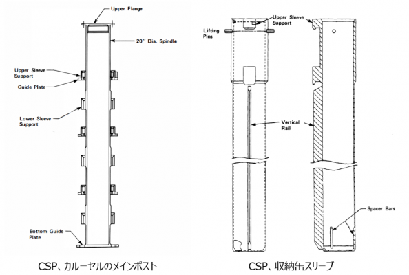 図14 (左) CPS主構造物(Spindle)、(右) 収納缶スリーブ [2,14}
 -
![図15 (左) スリーブハンドリングツール、(右) スリーブロッキングツール [2,14]](/wiki/nsfr_img_auth.php/thumb/d/d7/%E5%B7%A5%E6%B3%95%E3%83%84%E3%83%BC%E3%83%AB_34.png/417px-%E5%B7%A5%E6%B3%95%E3%83%84%E3%83%BC%E3%83%AB_34.png) 図15 (左) スリーブハンドリングツール、(右) スリーブロッキングツール [2,14]
図15 (左) スリーブハンドリングツール、(右) スリーブロッキングツール [2,14] -
![図16 (左) 収納缶のシールカバー、(右) 収納缶(単缶)ブラケット [2,14]](/wiki/nsfr_img_auth.php/thumb/a/a6/%E5%B7%A5%E6%B3%95%E3%83%84%E3%83%BC%E3%83%AB_35.png/559px-%E5%B7%A5%E6%B3%95%E3%83%84%E3%83%BC%E3%83%AB_35.png) 図16 (左) 収納缶のシールカバー、(右) 収納缶(単缶)ブラケット [2,14]
図16 (左) 収納缶のシールカバー、(右) 収納缶(単缶)ブラケット [2,14]
![図13 (左) CPSカルーセル外観、(中) CPSカルーセル縦断面、(右) CPSカルーセル水平断面 [2,14]](/wiki/index.php?title=%E3%83%95%E3%82%A1%E3%82%A4%E3%83%AB:%E5%B7%A5%E6%B3%95%E3%83%84%E3%83%BC%E3%83%AB_32.png)

![図15 (左) スリーブハンドリングツール、(右) スリーブロッキングツール [2,14]](/wiki/index.php?title=%E3%83%95%E3%82%A1%E3%82%A4%E3%83%AB:%E5%B7%A5%E6%B3%95%E3%83%84%E3%83%BC%E3%83%AB_34.png)
![図16 (左) 収納缶のシールカバー、(右) 収納缶(単缶)ブラケット [2,14]](/wiki/index.php?title=%E3%83%95%E3%82%A1%E3%82%A4%E3%83%AB:%E5%B7%A5%E6%B3%95%E3%83%84%E3%83%BC%E3%83%AB_35.png)
デブリ収納缶 [1]

収納缶設計方針
収納缶は、0.5ミクロンの微粒子から、燃料集合体の断面サイズまでの燃料デブリを回収できるように設計された。また、収納缶は、輸送キャスクを用いた構外輸送や、燃料デブリの長期保管のための、密封容器の役割も果たすように設計された。3タイプの収納缶が設計製作された(図18)[1]。
- Fuel収納缶: 大きな塊状デブリを直接回収、あるいは、別の小さな容器に回収した後で収納
- Knockout収納缶: 真空吸引システムにより、140ミクロンから燃料ペレット程度のサイズの粒子状デブリを回収(#粒径の大きい粒子をフィルター収納缶に送る前に、水流速を低下させ、水流の外に堆積させて除去する操作を"knockout"と呼ぶ)
- Filter収納缶: 真空吸引システムにより、Knockout canisterを通過した微粒子、水質浄化系を通過した微粒子、収納缶の脱水系を通過した微粒子、などを回収
収納缶の設計は、輸送や取り出し工程にも影響した。主要な設計因子は、臨界安全性、構造強度、冷却水の放射線分解、圧力容器内での取り扱い容易性、燃料移送系や輸送キャスクにおけるサイズや重量の制限、INELでの貯蔵プールでの重量制限、収納缶のベント、であった。#また、複数の単一目的の収納缶を設計するか、単一の多目的収納缶を設計するかが検討され、前者が選定された。NRCの輸送ライセンスに適合することも必要であった。
収納缶の設計では、当初の設計要求の外径13.35インチ(約32.5cm)から、14インチ(約34.3cm)に増やすことが検討された。これは、ホウ素遮蔽板の既製品サイズが14インチであったためだが、14インチ径では収納缶の水平断面が大きすぎ、取り扱いが難しくなるため、結局13.35インチに再設計された。しかし、小さい径の収納缶では、Knockout canisterの使用時に、流速を大きくする必要があり、小さい粒子の回収率が低下したのではないかと報告されている。また、形状の歪んだデブリや上部端栓の回収には、収納缶の内径がもう少し大きい方がよかったと報告されている。いくつかの上部端栓は、小分けするのが難しく、収納缶ではなく、貯蔵用のドラム缶に収納された。
燃料デブリ取り出しにおける重要なレッスンとして、次第に明らかになってくる内部の状況に基づいて設計の自由度を確保することと、設計や安全評価に必要となるリードタイム、の間のジレンマが指摘されている。収納缶についても、内部調査や、実際の使用経験に基づく、いくつかの改良が有効であった。1981年9月には、フルサイズの燃料集合体を格納できる収納缶が設計された。しかし、1983年8月の上部空洞ソナー調査とマッピングにより、フルスケールの燃料集合体はほとんど残留していないことが明らかになった。このことから、約4.3mのフルサイズ燃料集合体を収納できる当初の設計から、すでに承認されているM-130タイプの鉄道輸送キャスクを用いた経済的な構外輸送に適した、約3.3m長への設計変更が検討された。1984年6月に決定した仕様書では、収納缶の全長は約3.7mに増やされた。これは収納缶の製作業者が既存製造ラインで製作できる最大長さに相当した。収納缶長を短くすることで、取り扱い性は向上したと報告されている。また、さらに全長を半分に縮めた収納缶も検討されたが、充填されるデブリ重量が少なすぎるという観点で実現されなかった。
収納缶の重量測定
3タイプの収納缶に、圧力容器内で燃料デブリを充填する際の重量測定が大きな課題となった。アイダホ国立研究所の収納缶貯蔵プールの制限により、乾燥重量として輸送できる収納缶一体の重量は約1270kg(2800ポンド)が上限であった。圧力容器内での正確な重量測定にはいくつもの課題があった。デブリの密度が大きくばらついている可能性、重量測定中の圧力容器内の運転条件、収納缶高さ位置が数段階で異なること、収納缶を取り付けたカルーセルが回転すること、など。以下の重量測定方法が採用された。
- Fuel収納缶: 建屋クレーンで吊り下げて重量測定。Fuel収納缶は、デブリ回収作業中に上部が開放されており、運転員は、収納缶内部の充填率を目視しつつ作業できた。したがって、重量測定は、収納缶ごとに1-2回で充分であった。
- Knockout収納缶: 真空吸引作業中に、knockout収納缶に接続されたロードセルで連続的に重量測定された。このモジュールは、SWPの下面に取り付けられていた。
- Filter収納缶: 真空吸引作業中に、Filter収納缶に接続されたロードセルで連続的に重量測定された。同様に、SWPから吊り下げられていた。
- 脱水後の収納缶: 3タイプの収納缶ともに、不活性ガスのフローによる脱水処理がなされた後に、再度重量測定が行われた。収納缶内部の脱水処理前後で、輸送トロリーによって冷却水から引き揚げ、ロードセルにより、測定誤差約15kg(35ポンド)で重量測定された。
収納缶の充填剤
軽量コンクリート(セメント、ガラス材、脱塩水)が、Fuel収納缶の角型の内側シュラウドと円筒形の外管の間の充填剤に用いられ、両者の隙間が保持された。これにより、デブリ挿入時の内側シュラウドの変形やそれによる再臨界性の再評価必要性などが防止された。また、コンクリートを充填することで、冷却水中で収納缶が浮き上がることも防止された。しかし、収納缶の長期保管のためには、充填剤からの脱水が必要であり、INELでの、充填剤からの脱水作業は非常に困難であったと記載されている。また、デブリからの水素発生のため、収納管内の換気が必要であった。コンクリートの代わりの充填剤として、アルミナ粒子やグラスビーズもテストされた。
収納缶の除染
収納缶の外面線量は極めて高く、TMI-2サイト内での手作業でのスミアは不可能であった。TMI-2の燃料取扱い建屋において、輸送キャスクに装荷する途中で、収納缶表面は高温ホウ酸水のリング状スプレーで洗浄除染された。しかし、まだ、INELでの取り扱い基準の50倍の線量が残留していた。そこで、過酸化水素水溶液中に収納缶を浸した後、過酸化水素水にょるスプレーを行い、手作業でふき取りを行った。それでもまだ、さらに50%までの除染が必要であった。ブラシでこすった後にさらに手作業でふき取りしたが、まだ基準を満たすことができなかった。ブラシ磨きとふき取りの後に高温水洗浄することで、ほぼ基準がクリアされた。一方、INELでは、遠隔操作で、キャスクから取り出された収納缶のスミアが実施され、TMI-2での除染作業にフィードバックされた。
収納缶の数
コスト面での重要課題であったが、最終的に収納缶が何本必要になるかの判断は困難であった。当初見積もりでは、必要な収納缶数は243体とされた。アイダホ国立研究所の使用済み燃料プールの50%を利用することで、288体の収納缶を貯蔵することができると見積もられた。しかし、実際の燃料デブリ収納作業では、設計値に比べて少ない重量の燃料デブリしか収納缶に入れることができず、収納缶必要数が増加した。重要な点として、燃料デブリ取り出し方法が変更されたり、内部調査により炉内の状況が明らかになることで、3タイプの収納缶のそれぞれの必要数の見積もりが変化したことが指摘されている。最終的な必要本数の見積もり値は360体の間となった。燃料デブリ取り出し終了時点で、342体の収納缶が22回の列車輸送により、アイダホ国立研究所に輸送された。最終的な3タイプの使用実績は、Fuel canisterが286体、Knockout canisterが12体、Filter canisterが62体であった。
デブリ回収時の水質管理、作業性
デブリ回収作業中に、冷却水処理システム(DWCS)と添加剤の改良が必要となった。Filter収納缶の金属フィルターは、微生物の死骸と微粒子により目詰まりを起こした。過酸化水素水(殺生物剤)、珪藻土、凝固剤が、フィルターコーティング能力の向上のために用いられた。これらの材料は、デブリ取出しだけでなく、輸送や長期貯蔵にも使用された。また、水素触媒に、これらを混合させることで効果を高めることができたと報告されている。
圧力容器内冷却水の透明性は、作業効率や各種装置の破損リスクの低減に極めて重要であったことが報告されている。水質浄化系の基本設計は、濁度(NTU: nepkelometric turbidity)で0.1が設計目標とされた。6-10mの水深で遠隔手動でのオペレーションのためには、当初設計のNTU=1.0のかわりに、NTU=0.1に変更する必要があったと記載されている。圧力容器内の冷却水中での作業により、しばしば微粒子や微生物が巻き上がり、透明度が失われたことが報告されている。作業前には12mの透過度があったが、作業による懸濁で、1m以下の透明度になったことが報告されている。
事故直後の解析では、燃料集合体形状を維持したデブリがほとんどであると予想されていたが、上部ルースデブリサンプルの分析[8]により、粒子状デブリが多く存在することが明らかになった。溶融凝固デブリは、燃料集合体の主成分(U,Zr,Fe)と制御棒材(Ag,In,Cd)、その他の鋼材成分(Cr,Ni)からなっていた。また、酸素を多く含有していた。したがって、難燃性の酸化物が主成分であった。一部の溶融凝固物は、1m以上の厚みを持つ非均質な漏斗状の領域に存在していた(溶融凝固層)。別の一部は、バッフル板と圧力容器槽の間を通って下部プレナムに移行して堆積していた。このような溶融凝固物は数トン以上の重量があった。チゼルなどの機械的な破砕ツールでは、溶融凝固して一体化したデブリを破砕することができなかった。コアボーリングマシンやプラズマアーク切断機が必要となった。
デブリ回収ツール(初期)

真空吸引システム
前述の図3に、粒子デブリ、微粒子デブリの真空吸引システムの模式図を示している[2]。図19に、SWP下への真空吸引システムの設置外観図を示す[2]。
上部ルースデブリベッドに堆積していたデブリは、約20μmから約5mm程度のサイズが約90%を占めていることが、上部ルースデブリの分析により明らかになっていた[8]。そこで、粒子状デブリ回収の主要システムとして、2種類の収納缶(Knockout型、Filter型)と真空吸引ポンプを組み合わせた、水中での真空吸引システムが設計された。吸引ノズルから吸引された粒子デブリは、まず、Knockout収納缶を通過させる。ここではサイクロン方式で、収納缶内の水流速を低下させ、約140μm以上で、ペレットサイズ程度までの粒子デブリが回収される。ついで、バックアップを含む2系統のFilter収納缶を通過させ、0.4μmメッシュの金属フィルターでデブリ微粒子デブリがろ過して回収される。処理後の冷却水は、圧力容器内に還流される。Kockout収納缶のフィルターが詰まりやすいため、バックフラッシングのラインが取り付けられている。前述の図5に示すように、真空吸引システム(図19)は、SWP下に取り付けられていた。なお、この図では、Knockout収納缶は、直接SWPから吊り下げられているが、上述のCPSカルーセルのSleeve中にKnockout収納缶を装荷する方式も検討された。この場合には、Sleeve内のKnockout収納缶の上部に接続ポートが取り付けられる構成であった。
しかし、実際に運用してみると、バックフラッシングしてもフィルターのつまりが解消されにくく、あまりデブリの回収効率が上がらないことが明らかになった[15]。したがって、初期のデブリ取り出しでは、真空吸引システムより、スペード型のデブリバケツ(後述)によるPick-and-Place工法が多用された。したがって、Knockout収納缶はあまり使用されなかった。
一方で、図19と同等の真空吸引システムが、デブリ収納缶貯蔵プールの冷却水浄化系に設置さた。こちらはデブリ取り出しの全期間を通じて利用された。
.
真空吸引システムの主要機器は、ノズルアッセンブリ、ポンプモジュール、Knockout収納缶コネクション、Filter収納缶コネクション、運転をサポートする長尺ツール(オペレーショングラップル、ホースハンドリング、接続外しツール)、などであった。Knockout収納缶、Filter収納缶の重量はロードセルで連続的に秤量され、重量が許容値を超えると警報が発報する設計であった。
図20に、真空吸引システム操作用の各種ツール(グラップラー、クイックカップラー、ホースハンドリングツール、ソケットレンチ、フックツール、ホース接続ツール)、及び、真空吸引ホースシステムをそれぞれ示す[2,14]。
-
![図20(a) 真空吸引システム用の各種長尺ツール [2,14]](/wiki/nsfr_img_auth.php/thumb/2/2b/%E5%B7%A5%E6%B3%95%E3%83%84%E3%83%BC%E3%83%AB_14.png/480px-%E5%B7%A5%E6%B3%95%E3%83%84%E3%83%BC%E3%83%AB_14.png) 図20(a) 真空吸引システム用の各種長尺ツール [2,14]
図20(a) 真空吸引システム用の各種長尺ツール [2,14] -
![図20(b) 真空吸引システム用の各種長尺ツール [2,14]](/wiki/nsfr_img_auth.php/thumb/3/3b/%E5%B7%A5%E6%B3%95%E3%83%84%E3%83%BC%E3%83%AB_15.png/480px-%E5%B7%A5%E6%B3%95%E3%83%84%E3%83%BC%E3%83%AB_15.png) 図20(b) 真空吸引システム用の各種長尺ツール [2,14]
図20(b) 真空吸引システム用の各種長尺ツール [2,14] -
![図20(c) 真空吸引ホースシステム [2,14]](/wiki/nsfr_img_auth.php/thumb/2/28/%E5%B7%A5%E6%B3%95%E3%83%84%E3%83%BC%E3%83%AB_16.png/223px-%E5%B7%A5%E6%B3%95%E3%83%84%E3%83%BC%E3%83%AB_16.png) 図20(c) 真空吸引ホースシステム [2,14]
図20(c) 真空吸引ホースシステム [2,14]
![図20(a) 真空吸引システム用の各種長尺ツール [2,14]](/wiki/index.php?title=%E3%83%95%E3%82%A1%E3%82%A4%E3%83%AB:%E5%B7%A5%E6%B3%95%E3%83%84%E3%83%BC%E3%83%AB_14.png)
![図20(b) 真空吸引システム用の各種長尺ツール [2,14]](/wiki/index.php?title=%E3%83%95%E3%82%A1%E3%82%A4%E3%83%AB:%E5%B7%A5%E6%B3%95%E3%83%84%E3%83%BC%E3%83%AB_15.png)
![図20(c) 真空吸引ホースシステム [2,14]](/wiki/index.php?title=%E3%83%95%E3%82%A1%E3%82%A4%E3%83%AB:%E5%B7%A5%E6%B3%95%E3%83%84%E3%83%BC%E3%83%AB_16.png)
Pick-and-Place工法用の長尺ツール
Pick-and-Place工法用の長尺ツールは、重量ツールと軽量ツールに大別される。複数タイプの先端構造が設計・検討された。機能確認試験が入念に行われ、作業スペースの効率化や汚染の抑制の観点で、実機投入する先端ツール(End Effector)が選定された[2,14]。表2に、設計された長尺ツールの一覧を示す[2]。
| ツール/コンポネント | 英語名 | 用途 |
|---|---|---|
| 重量ツール(ジブクレーンで重量保持) | ||
| 先端ツール取り扱いツール | End Effector Handling Tool | ハンドリングツールの先端に、各種のEnd Effectorを、用途によって着脱して使用。また、稼働用の油圧系統を内部に配管。最大荷重約900kg。最大横荷重約60kg。
End Effectorは、遠隔操作ボルトと油圧式のクイックカップリング(SS304製)で着脱。 ポールは、約6.7mの主ポールと約2.1mのサブポールの連結方式で、長さを三段階調整可能。総重量約123kg(End Effectorを含む)(図21(左))[2] |
| 三点グリッパー | Three Point Gripper | 小サイズの瓦礫デブリを摘まみ上げ。最大取り扱いサイズ:約15cm幅、約9kg以下。(図21(右))[2] |
| 四点グリッパー
(はさみつけ引き抜き) |
Four Point Gripper
(Staple Puller) |
不規則形状のデブリ粒子を摘まみ上げ、あるいは、横倒しのデブリ瓦礫を立たせる。約7mm~約10cmの棒状デブリが主な対象。(図22(左))[2] |
| グラップル | Grapple | 不規則形状のデブリを引き起こし。主な対象は、上部端栓やスパイダーなどの構造物。(図22(中))[2] |
| 単一棒のシャーリング | Single Rod Shears | ハサミ形式の先端構造(右手用、左手用)。AISI鋼製。固定側のブレードを燃料棒などの単管に打ち込み、反対側の可動式ブレードで挟み付けて切断。油圧約10MPaで切断荷重約2.3トン。
このツールの設計詳細は、実際に模擬燃料簿の切断試験を行って決定された。(図22(右))[2] |
| 分離くさび | Parting Wedge | 凝集したデブリの隙間に差し込み、分割するツール。約14MPaの油圧で、先端に約230kgの荷重。約20cm長さの先端アームにより、約18cmの開口が可能。(図23(左))[2] |
| 重量物トング | Heavy Duty Tong Tool | 重量デブリを挟み込んで吊り上げ。最大約25cmの幅まで対応。挟み込み圧力は約3.4MPa。(図23(右))[2] |
| スペード型バケツ(シャベル) | Spade Bucket Tool | 小サイズから中サイズまでの粒子状デブリを掬い取り、あるいは掘り出し。固定された水平プレート面(バケツの蓋)と油圧駆動のバケツ(シャベル)。掬い取り作業の油圧は約3.4MPa。(図24(左))[2] |
| クラムシェル型サンプラー | Clamshell Tool | 最大約15cm径より細い領域に侵入させ、粒子状のデブリを挟み付けて回収。2個の早退する三角形ブレードで挟み込む。最大約110kgまで回収可能。最長約2m深さまで侵入可能。油圧は約3.4MPa。(図24(右))[2] #上部ルースデブリのサンプリングツールと類似した構造。 |
| 重量物のシャーリング | Heavy Duty Shears | 崩落していた上部端栓から、燃料棒を切断除去用。横倒した燃料集合体を複数回のシャーリングで切断可能。通常の使用済み燃料シャーリングで使用されるHurstカッターブレードを使用。約17cmの開口部。(図25)[2] |
| 軽量ツール(アルミニウム製の導管の先端に取付。ジブクレーンでの吊り下げはケースバイケースで選択。小回りの必要な作業に使用。) | ||
| プライヤー | Vise Grips | プライヤーー形状の先端ツールを、目的によって様々に交換して使用。挟み付け、摘まみ上げ、かきとり、掬い取り、など。(図26(左))[2] |
| ボルトカッター | Bolt Cutter | 約680~820kgの荷重範囲。ボルト先端の切断。(図26(右))[2] |
| フックツール | Hook Tool | ひっかけあげ。最大約23kgまで。(図27(左))[2] |
| ソケットレンチ | Socket Wrench | 重量ツールのEnd Effector交換作業用。(図27(左中))[2] |
| メジャー | Measuring Probe | 約4mまでのスケールを記載。(図27(右中))[2] |
| 軽量物トング | Light Duty Tong | 最大約45kgまでの軽量デブリをはさんで、摘まみ上げ。(図27(右))[2] |
| 端栓装荷ツール | End Fitting Loading Tool | 上部端栓のサイズは、Fuel収納缶の内側サイズぎりぎりでクリアランスが小さいため、端栓を正確に収納缶内に装荷するためのツール。最大約900kgまで取り扱い可能。(図28(左))[2] |
| バンドツール | Banding Tool | ピボット方式での圧着、バンドを巻いて締め上げるツール。切断にも使用。巻き付け最大荷重は約250kg。破損燃料集合体のシャーリングの前に、複数燃料棒を束ねるために使用。(図28(右))[2] |
| デブリバケツハンドリングツール | Debris Bucket Handling Tool | デブリバケツに取り付けられたリフトタブをひっかけて引き上げ、使い捨てデブリバケツをFuel収納缶に挿入し、リフトを取り外すように設計。(図29(左))[2] |
| ハンドレール油圧パネル | Handrail Hydraulic Panel | Banding toolとClamping Stationへの油圧供給の中継地点。高圧油圧系と低圧油圧系。長尺ツール取り扱いスロットのハンドレールに取付。 |
| サポート設備(将来、圧力容器内のスペースが確保された設置予定) | ||
| 使い捨てデブリバケツ | Disposable Debris Buckets | Fuel収納缶内に収まる形状で、縦型と横型の2種類製作。メッシュ構造の本体に、蓋つき。縦型バケツは、上部に蝶番形式のメッシュ蓋つき。横型バケツは、横倒しにしてデブリバケツスタンドの上に配置することで、側面に蝶番蓋が位置する構造。吊り上げた部が取り付けられており、上述のハンドリングツールでひっかけて移動。そのままFuel収納缶に装荷」。(図29(中、右))[2] |
| 再利用デブリバケツ | Reusable Debris Buckets | 再利用型のデブリバケツ。いったんデブリを収納し、下部の蝶番蓋を開くことで、デブリ漏斗を通じて、Fuel収納缶内にデブリを投入する仕組み。(図30(左))[2] |
| デブリ漏斗 | Debris Bucket Funnel | Fuel収納缶の上に設置し、再利用タイプのデブリバケツからデブリを落とし込む作業で使用。(図30(右上))[2] |
| 下部端栓ワイヤー用の貯蔵バスケット | End Fitting Wire Storage Busket | 切断したインコアモニターワイヤーなどの構造材由来のデブリを貯蔵するバスケット。(図30(右下))[2] |
| デブリバケツスタンド | Top Loading and Side Loading Debris Bucket Stands | デブリバケツ内にデブリを回収する作業の間、デブリバケツを縦置き、あるいは横置きで保持。下部格子の上、あるいは、バッフル板の上に取り付けられる構造。取付はソケットレンチ(上述)で実施。(図31)[2] |
| デブスタンドハンドリングツール | Debris Stand Handling Tool | デブリスタンドのハンドリングツール。(図32)[2] |
| デブリクランプステーション | Debris Clamping Station | 上部端栓、スパイダー、燃料集合体、などの一部を、切断、バンド掛けなどの作業のために、挟み付けてホールド(縦置き方向、横置き方向)。(図33(左)) |
| デブリバケツハンガー | Debris Bucket Hanger | SWPの下で、様々なタイプのデブリバケツを一時保持。ピボット構造で水平位置を可変。用いないときには、回転させて、作業域から離れたとことに移動。
圧力容器内での、2つのスロット間でのデブリ移送にも使用。 支持ポスト、軸方向延長配管(ピボットタイプ)、径方向アーム、外側ピボット、デブリバケツトレー、で構成。(図33(右)) |
-
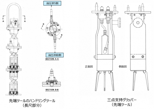 図21 (左)、(右)
 -
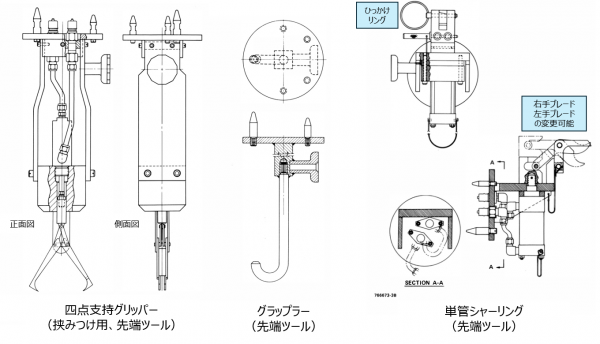 図21 (左)、(中)、(右)


-
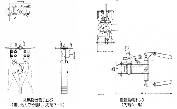 図21 (左)、(右)
 -
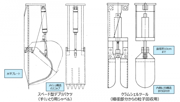 図21 (左)、(中)、(右)


-
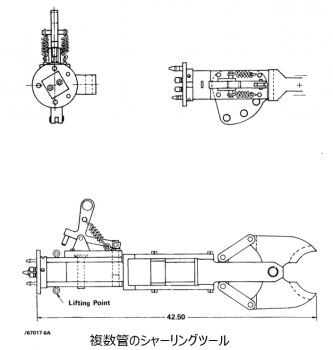 図21 (左)、(右)
 -
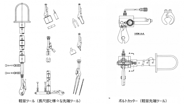 図21 (左)、(右)


-
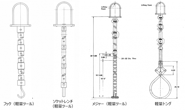 図21 (左)、(右)
 -
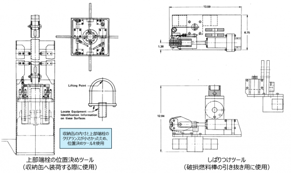 図21 (左)、(右)


-
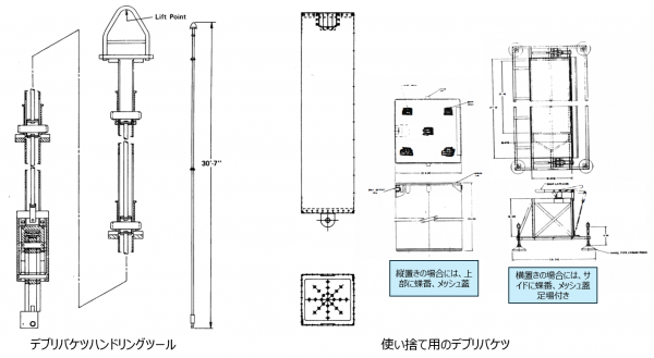 図21 (左)、(右)
 -
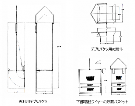 図21 (左)、(右)


-
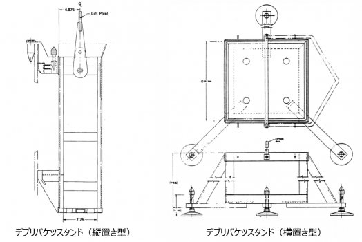 図21 (左)、(右)
 -
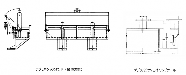 図21 (左)、(右)
 -
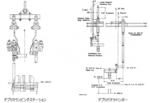 図21 (左)、(右)


制御用設備、観測系設備
真空吸引システム、及び、Pick-and-Place用の長尺ツールでのデブリ回収をサポートする設備として
- 電気系統、配電盤
- 制御パネル
- 油圧系統
- ケーブルマネージメントシステム
が、設置された。詳細省略。
また、デブリの真空吸引、Pick-and-Place操作、収納缶回収、収納缶挿入、などの作業の観測系設備として、
- ビデオ
- ビデオカメラハンドリングツール
- ライト
- 真空吸引ノズルの観測系
- 計測器
などが取り付けられた。
-
![図13 (左) CPSカルーセル外観、(中) CPSカルーセル縦断面、(右) CPSカルーセル水平断面 [2,14]](/wiki/nsfr_img_auth.php/thumb/2/2d/%E5%B7%A5%E6%B3%95%E3%83%84%E3%83%BC%E3%83%AB_30.png/304px-%E5%B7%A5%E6%B3%95%E3%83%84%E3%83%BC%E3%83%AB_30.png) 図13 (左) CPSカルーセル外観、(中) CPSカルーセル縦断面、(右) CPSカルーセル水平断面 [2,14]
図13 (左) CPSカルーセル外観、(中) CPSカルーセル縦断面、(右) CPSカルーセル水平断面 [2,14] -
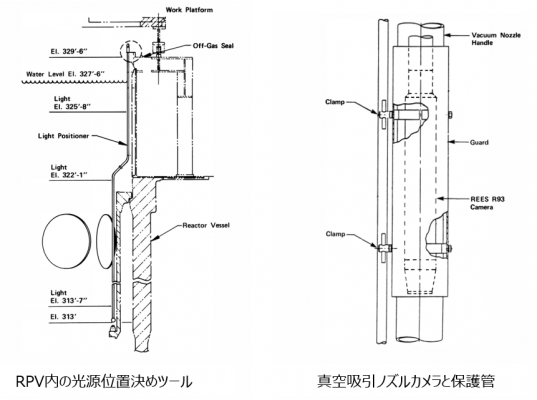 図14 (左) CPS主構造物(Spindle)、(右) 収納缶スリーブ [2,14}
![図13 (左) CPSカルーセル外観、(中) CPSカルーセル縦断面、(右) CPSカルーセル水平断面 [2,14]](/wiki/index.php?title=%E3%83%95%E3%82%A1%E3%82%A4%E3%83%AB:%E5%B7%A5%E6%B3%95%E3%83%84%E3%83%BC%E3%83%AB_30.png)

溶融凝固層の破砕ツール
ルースデブリ回収後には、溶融凝固デブリ層と推定される硬いデブリ層を破砕し、回収する必要があると考えられた。この作業のための、End Effectorの基本的な検討が、上部ルースデブリの回収作業に並行して行われた[2]。これら、取り出し後期で必要となるツールについても、基本的には、End Effector Handling Toolに取り付けて、作業を行うことが検討された。

打撃チゼル
溶融凝固デブリを破砕、あるいは、掘削する目的で、油圧式のチゼルが設計された(図34(左))[2]。一分あたり2000回の打撃と3.5rpmでの回転ができるように設計された。
研磨ソー
溶融凝固デブリを切断する目的で設計された(図34(右))[2]。打撃チゼルと同程度の油圧で稼働し、8インチ幅の円形ソーで2インチ深さまでの切断が、10インチ幅の円形ソーで3インチまfrの切断が可能であった。
水圧レーザー(Hydrolaser)
高圧水によるデブリ切断システムが検討された。高圧ノズル、高圧ポンプ、水流混合ボックス(WC製)、などの付属設備が必要となる。
#しかし、これらのツールは実際にはほとんど使用されなかった。打撃チゼルは、コアボーリング作業後に使用されたが、デブリ破砕効率が悪かったため、ボーリング装置の先端ビットを交換してのボーリング破砕作業に振り替えられた。研磨ソーは、デブリ切断にはほとんど使用されず、主に、炉心支持構造物の縦方向の配管の切断用に用いられた。また、類似構造を持つ付着デブリの研磨機として使用された。水圧レーザーもほとんど使用されず、代替として、スライドハンマーが用いられた。
位置決めシステム(Tool Positioning)
デブリ取り出し後期には、炉心下部支持構造物(LCSA)の全範囲にアクセスする必要がある。取り出し初期に使用されるツールを用いて、SWPから、すべてのLCSA範囲にアクセスするのは困難であり、収納缶や各種取り出しツールについて、なんらかの移送や回転システムが必要になると考えられた。#実際には、炉心下部の燃料集合体は、上部をバンドして下部格子から引き抜き、あるいは、爪状のツールを下部に差し込んで引き抜きされた。また、LCSAの切断には、アークプラズマ方式の切断システムが用いられた(後述)。デブリ回収には、エアリフトが用いられた(後述)。
ROSA[11]、MANFRED[12]
デブリ取り出し後期では、溶融凝固デブリを破砕し、回収する必要がある。この作業を自動で行うシステムとして設計されたが、実機投入されなかった。
コアボーリングマシン(CBM)

Quick Look調査[3]や上部ルースベッドの探針調査[5]などにより、炉心上部の燃料が崩落して上部空洞とルースブリベッドが形成されていること、また、デブリベッドの堆積厚さは約0.6~0.9mであり、その下には探針が貫通できない硬い層が存在していることが明らかになった。一方で、コアフォーマと圧力容器槽の円環状の隙間を通じて行われた下部プレナム周辺部の調査[10]により、約10~20トンのデブリが下部プレナム内に堆積していること、炉心下部構造物(LCSA)にはほとんど損傷が見られないことが明らかになった。これらのことから、炉心下部には溶融凝固層と切り株状に残留した燃料集合体が存在していることが推定された。それらの堆積状態を調査することで、炉心下部からのデブリ取り出し工法の具体化と、事故時のデブリふるまいの解明に極めて有用な知見が取得できると判断され、コアボーリング調査が行われることとなった[16]。なお、コアボーリング調査が行われるまでは、溶融凝固層の中央底部が破損し、溶融デブリはLCSAの中央を破って、下部プレナムに移行したと推定されていた[16]。しかし、実際には、ほとんどの溶融デブリは、炉心南東側のバッフル板を破り、コアフォーマ領域を通過して下部プレナムに移行していたことがボーリング調査で明らかになった[16]。
参考:Quick Look調査
参考:DOE年次レポートの概要(上部ルースデブリ採集、1983年レポート)
参考:下部プレナム調査
コアボーリングマシンの設計と据え付け

コアボーリング装置の設計要件として、以下が提示された[17]。
- 2.4m長さ、6.35cm径のサンプルを回収できること(Fuel型収納缶に収納できるサイズ)
- 回収したサンプルをFuel収納缶に装荷できること(RPV内でのデブリ取り扱いシステムを使用)
- 炉心中央から、2.4m径の範囲でボーリング可能なこと(SWP: Shielded Working Platformの上に設置したドリルマシンからのドリルビットの到達範囲)
- 装置をモジュール化し、エアロックを通じて原子炉建屋内に搬入し、SWP上で組み立てられること
- 4つのカテゴリーの層を掘削できること(形状を維持した燃料集合体、ルースデブリベッド、溶融凝固層(セラミックと金属混在)、空洞)
- 作業員の数と作業時間を最小化すること
高線量下で使用可能で、経済的に合理的、という観点で、様々な方式のコアボーリングシステムが検討され、アイダホ国立研究所(INEL)で機能確認試験が行われた。機能確認試験では、ジルカロイ被覆でSiO2ペレットからなる模擬燃料棒、インコネル製のスペーサーグリッド、ステンレス製の端栓、コンクリートブロック、砂利、アルミナ板などが用いられた。
まず、先端に取り付けるドリルビットの開発が行われた。図23に、市販品をベースに開発されたドリルビットを示す[18]。鋳造された王冠構造であり、その内外面には工業用ダイヤが塗布されている。また、先端にはタングステンカーバイド性の刃が銀はんだで取り付けられており、刃部分にも工業ダイヤが塗布されている。
次に、このドリルビットをとりつけるドリルユニットの選定が行われた。Longyear社の製品をベースに機能確認試験が行われ、回転速度、トルク、先端荷重などの範囲が選定された。その結果に基づいて、ドリルストリングの構造や回転駆動力の伝達メカニズム、サポートツールの構成等が設計された。コアボーリングマシンの設置概念図を図24に示す[18]。
ドリルストリング(パイプ)はシリンダー形状で、装置の上部から挿入される。途中に3か所の接続部(クランプ)があり、ドリルビットに回転駆動力と荷重を伝える。シリンダーは二重管になっており、外管はドリルの軸を支持する役割もになっている。ドリルストリングは、日本製のMagaloヘッドに取り付けられている。回転速度は0~500rpm、トルクは0~4067J、荷重は0~4535kgで、それぞれ可変である。ドリルストリングの先端部分は、サンプルを回収するコアバレル、ドリルストリング、およびケーシングからなっており、ドリルストリングは必要な深さまで到達する長さになっている(#それ以下までストッパーにより侵入しない。インコアモニターノズルを破損させないため)。ケーシングは、コアバレルを回収した後に、下部プレナムにビデオを挿入する通路を保持する役割もになっている。コアバレルは、市販品ベースで、サンプルを保持し、ドリルビットを支持し、駆動力を伝え、冷却水を供給する役割を持っている。二重管で、内側はサンプルを保持、外側はビットを回転させる役割である。コアバレル内にサンプルが侵入することで内部の水が押し出されるため、その排水口が上部に設けられている。ドリルストリング(8.9cm外径)とケーシング(11.4cm外径)は既製品が利用された(#全長は短尺化された)。ケーシングの内径10.2cmとドリルストリングの間を維持するように、ドリルストリング側にスペーサーが溶接された。作業中に、ビットの冷却と掘削粒子の除去のために、ホウ酸水の連続供給が行われた。作業後の、ケーシングとドリルストリングの除染用にホウ酸水スプレーが取り付けられた。加圧ポンプにより、RPV内の冷却水を使用して冷却水が供給された。一方、除染にはフレッシュな冷却水が用いられた。TMI-2のホウ酸水調製設備で製造されたホウ酸がいったんタンクに貯蔵され使用された。

SWPの上に、インターフェースプラットフォーム、ドリルの位置決めプラットフォーム(インデックスプラットフォーム、径方向移動と回転移動の2種類)、作業員の手すり用プラットフォーム(Tilt Platform)が、それぞれ取り付けられ、その上にドリルマシンが組み立てられた。Tiltプラットフォームは、作業スペースとしても利用された。SWPには36cm径の開口部が数カ所設けられており、これらのプラットフォームを組み合わせて動作することで、炉心中央から2.4m径の範囲のどこでもボーリング作業ができるように設計された。また、装置の水平維持のため、位置決めプラットフォームの下に油圧ジャッキ4基が設置された。さらに、水中でドリルストリングを保持する支持構造物がSWPの底面に取り付けられた。
コアバレル内にサンプルが回収された後、RPV内の上部に引き上げられ、鉛遮蔽付きの輸送キャスク内に収納された。輸送キャスク表面は、キャスクスプレーによりホウ酸水で洗浄された。この他に、ホウ酸水供給系(加圧ポンプとホース)、サンプルの酸化を防止するために、輸送キャスク内を不活性ガスでパージするシステム、収納缶に入れる前にサンプルをいったん保持する貯蔵バスケット、ドリルマシンの制御盤、ビデオモニター系が取り付けられた。安全系統として、ドリルビットへの冷却水水圧と水流、クランプ部のねじれトルク、油圧媒体の容積と温度などが連続的にモニターされ、設定リミットを超えた場合に、装置が自動停止するように設計された。
また、モックアップ試験では、掘削層が変化した際の各種運転パラメータの変化傾向が調査された。これにより、掘削中のパラメータ変化により、コンピューター解析で成層化の状態が表示されるようになった。図25に、モックアップ試験でのパラメータ変化の例を示す[16]。
コアボーリングの作業手順
- ドリルマシンをインデックスプラットフォーム上に組み立て
- ボーリングの目標地点に位置決め
- ドリルパイプとケーシングを組み立て、クランプで保持
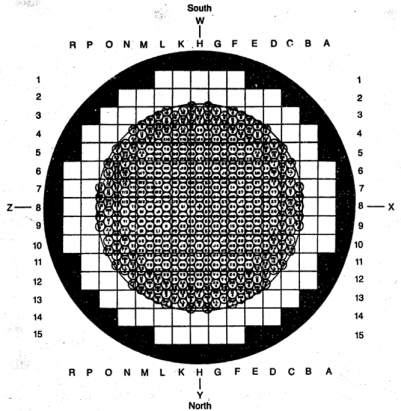
図26 溶融凝固層の破砕作業(スイスチーズ化) [15] - コアバレルとドリルストリングを下降、ボーリング開始
- 下部端栓位置を貫通したら、ボーリング操作を一旦停止
- LCSAの第1層の上でコアバレルを保持し、ケーシングの上部にプラグ取り付け
- ドリル開口部にケーシングを挿入し、開口部を保持
- ケーシング上部を取り外し、コアバレルを鉛遮蔽つきの輸送キャスク内に引き上げ
- 輸送キャスク内を窒素ガスパージし、Fuel収納缶の上に移動
- コアバレルを収納缶内に格納
- 必要に応じ、ケーシング内にビデオカメラを挿入し、下部プレナム領域のビデオ撮影
- 必要に応じ、小径のドリルストリングを入れて、LCSA以下のコアボーリング(#デブリがLCSA内に多く堆積していた場合)
- 必要に応じ、下部端栓部分の開口部をふさぐプラグ装荷(#上部からのデブリ落下防止
- 下部プレナムデブリサンプルを既存の長尺ツールで採集
- 作業後にマシン解体、除染

溶融凝固層の破砕作業
CBMは、ボーリング調査後に、先端ビットと硬い固体形状に交換して、溶融凝固層の破砕作業(スイスチーズ化)に用いられた[7]。図26に、掘削軸を重ねながら実施された400カ所のボーリング位置を示す[15]。
LCSAの切断・解体作業
CBMは、さらに、5層構造からなる炉心下部構造物(LCSA: Lower Core Support Assembly)の第1層と第2層について、支持ポストやインコア案内管の切断に用いられた。図27に、LCSAの構造を示す[19]。縦方向に、構造物が入っていることがわかる。LCSA解体作業の詳細は別項目で説明する。

デブリ取り出し後期に用いられたシステム
ここから、、、参考文献確認
プラズマアーク切断システム


炉心下部構造物(LCSA: Lower Core Support Assembly)や炉心上部構造物(UCSA: Upper Core Support Assembly)の切断/解体に用いられた、自動化切断システム(ACES: Automated Cutting Equipment System)の模式図を図7(a)に示す[6]。この装置は、LCSAの上に設置されたX-Yブリッジを使って、プラズマアークトーチを5軸で稼働させる仕組みであった。図7(b)に、5軸の概念図を示す[9]。キャリッジとトロリーで、トーチを
プラズマアーク切断法は、様々な切断方法(ウォータージェット、シャーリング、アークソー、酸素燃焼、超音波破断、レーザー切断など)の中から選定され、
デブリ取り出し初期には、炉心上部格子や端栓の解体に利用された。LCSAの解体/取り出しでは、約1年かけて約50個のパーツに解体された。解体作業自体は短時間であったが、システムの不具合や設計変更に時間を要したと報告されている。
プラズマアーク切断機では、トーチの焼け付きの他に、電気系統、シール、などのトラブルが発生した。およそ10回の切断に1回の割合でトーチが焼け付き、交換が必要となった。これは、ホウ酸水の電導性がよいために発生した。焼き付きのたびに、装置をSWPまで引き上げ、交換/整備する必要があった。構造物に燃料デブリが固着している個所では、プラズマアークでの切断は困難であった。トーチの振動や汚染も課題であった。また、アーク溶融による切断の副生成物として、核燃料物質の蒸発、Kr-85の放出、CO発生、水素発生、NOx発生、Niカルボニール蒸発等が課題となった。特に窒素酸化物が多く発生しその処理が重要課題となった。これらのうち、Kr-85以外は、SWPに取り付けたオフガス処理系で回収した。凝集性のガス成分は、圧力容器内の冷却水中に戻した。Kr-85については環境に放出するオフガスをモニターする必要があった。[1]
エアリフト
エアリフトの概念図を図3に示す。燃料デブリを真空吸引システム、あるいは、エアリフト内に吸入するためには、1.5-3.0 m/sの冷却水の吸引流速が必要であった。吸引ノズル先端とデブリとの距離を、ノズル径よりも近くすると、燃料デブリを効率的に吸引できた。エアリフトにおける大きな課題は、透明度の喪失と、小サイズから中程度のサイズの粒子が、圧力容器内の様々な水平方向の面で移動して再分布することであった。これらの課題は、冷却水処理系のフィルターを改良することで、回収時間を4時間から2時間に短縮する程度に、若干改善された。類似作業の際には、すべてのタイプの粒子を同一シリーズのフィルター装置で回収していたが、条件によっては、追加フィルターを取り付けることで、燃料回収が効率化した可能性があることが指摘されている。
エアリフトシステム(ALS: Air-lift system)を使うことで、上部ルースベッドや下部ヘッド堆積物から、何トンもの燃料デブリが効率的に回収されている。燃料デブリと冷却水と空気を分離する技術により、デブリバケツ中にデブリが効率的に回収され、収納缶に挿入された。ALSにより、圧搾空気を用いて、LCSAの下に堆積していた燃料デブリ(酸化物系の瓦礫)も、効率的に、デブリバケツ内に移送された。バケツ内や収納缶内では、重力沈降により、燃料デブリ成分と冷却水や空気が分離された。駆動部分の信頼性が十分でなかったため、アイダホ国立研究所で、鉛の削りくず、2.5cm角の塊、いろいろなサイズの粒子、1cm径のステンレス配管を2-5cmくらいに切ったもの、を入れたタンクの底に、LCSAのモックアップを設置して、ALSのフルスケールモックアップ試験が行われた。モックアップ試験により、最低でも230kg/mの処理速度で、模擬燃料デブリがデブリバケツ内に移送できることが確認された。[1]
様々な構造物の回収作業
燃料集合体
炉心外周部には、様々な長さの燃料集合体が残留していた。最初の一体目を、投げ縄方式で引き抜いた後は、比較的容易に支持格子から引き抜くことができた。引き抜きには、油圧式のサイドグリッパー、スピア、L型の集合体リフターが用いられた。
インコアモニターの案内管
インコアモニター案内管とその支持ポストの切断には(図2参照)、コアボーリングマシン操作に習熟が必要であった。切断を効率的に行うには、削り屑が下に落ちるためのスペースが必要であったと報告されている。
バッフル板
バッフル板は、炉心外周に垂直に立っていた。約4tの燃料デブリが、バッフル板を破損して、その外側のコアフォーマ領域に侵入し、堆積していた。この極めて高線量のバッフル板を解体するために、いくつかのオプションが検討された。ガンマ線計測から、バッフル板の線量は、大気中に引き上げた場合、約30Sv/hと推定された。オプション1:バッフル板をいくつかの小さいピースに切断し、Fuel canister、あるいは、別に設計した収納缶に入れて引き上げる。オプション2:いくつかのピースに分割したバッフル板を取り出し、収納缶に入れずに、遠隔で保管する(貯蔵の候補地としては、原子炉建屋の地下階、改良した貯蔵タンクが検討された。#炉心下部支持格子の一部は、貯蔵タンク内に格納されていた)。オプション3:バッフル板をいくつかの大きなピースに切断し、それを90度ひっくり返してから、燃料デブリを回収する。このうちで、オプション3が選択された。その選択理由は、プラントの改良が必要なく、作業員の被ばく量が少ないこと、製作するツールが最も少なくて済むこと、追加で検討すべき安全性課題がないこと、であった。
バッフル板はプラズマアーク切断機で8個に分割され、864個の絶族ボルトはトルクレンチツールとドリルマシンで除去された。約4m長のステンレス製バッフル板は、強く放射化されていた(約30Sv/h)。バッフル板の取り外しにより、コアフォーマ領域のデブリが露出された。バッフル板は先に2枚が取り外され、ベント弁シートから吊り下げられ、燃料デブリの除去が行われた。その後、次の2枚が同じように処理された。コンピューターシミュレーションにより、バッフル板の効率的な取り外しの順番が決められた。
参考文献
[1] R. Brown, US-DOE Three Mile Island Research and Development Program 1985 Annual Report, GEND-055, 1986.
[2] Bechtel North American Power Corporation, TMI-2 Defueling Tools Engineering Report, GEND-INF-073, 1986.
[3] Quick Look Inspection: Report on the Insertion of a Camera into the TMI-2 Reactor Vessel through a Leadscrew Opening, vol. 1, GEND-030, 1983.
[4] R.W. Garner, D.E. Owen, M.R. Martin, An assessment of the TMI-2 Axial Power-shaping rod dynamic test results, GEND-INF-038, 1983.
[5] D.E. Scardena, TMI-2 Technical Information and Examination Program 1983 Annual Report, GEND-039, 1984.
[6] L.S. Beller and H.L. Brown, Design and Operation of the Core Topography Data Acquisition System for TMI-2, GEND-INF-012, 1984.
[7] K. Vinjamuri, D.W. Akers, R.R. Hobbins, Examination of H8 and B8 Leadscrews from Three Mile Island Unit 2 (TMI-2), GEND-INF-052,1985.
[8] D.W. Akers, E.R. Carlson, B.A. Cook, S.A. Ploger and J.O. Carlson, TMI-2 Core Debris Grab Samples -Examination and Analysis, GEND-INF-075-PT1 and GEND-INF-075-PT2, 1986.
[9] Technical Integration Office, TMI-2 Information and Examination Program 1981 Annual Report, GEND-022, 1982.
[10] J.P. Adams, R.P. Smith, TMI-2 Lower Plenum Video Data Summary, EGG-TMI-7429, 1987.
[11] C.J. Hess, TMI-2 Technical Information and Examination Program 1984 Annual Report, GEND-049, 1985.
[12] R.F. Ryan and R. Blumberg, Lower Core Support Assembly Defueling Plans and Tools, GEND-INF-093, 1988.
[13] H. George, Control of Heavy Loads at Nuclear Power Plants: Resolution of Generic Technical Activity A-36, NUREG-0612, 1980.
[14] D.E. Falk and C.E. Swenson, TMI-2 Defueling System Design Description, GEND-INF-065, 1985.
[15] US-DOE, Three Mile Island Research and Development Program 1986 Annual Report, 1987.
[16] J.M. Rodabaugh and D.K. Cowser, Three Mile Island Unit 2 Core Region Defueling, Nucl. Technol. 87 (1989) 1112-1116.
[17] E.L. Tolman et al., TMI-2 Core Bore Acquisition Summary Report, EGG-TMI-7385, 1987.
[18] K.M. Croft et al., TMI-2 Core Boring Machine, EGG-M-08986, 1986.
[19] A.W. Marley, D.W. Akers and C.V. Mclsaac, Sampling and Examination Methods Used for Three Mile Island Unit 2, Nucl. Technol. 87 (1989) 845-856.
[20] H.M. Burton and R.L. Freemerman, Reactor Disassembly Activities at Three Mile Island Unit Two, Progress in Nucl. Energy, 17 (1986) 141-174.
---
[6] P.L. Winston, Management of the Three Mile Island Unit 2 Accident Corium and Severely Damaged Fuel Debris, Contribution to International Atomic Energy Agency Coordinated Research Proposal T13015, INL-EXT-21-61607, rev. 2, 2022.
[11] M.S. McGough et al., Performance of the Automated Cutting Equipment System During the Plasma Cutting of the Three Mile Island Unit 2 Lower Core Support Assembly, Nucl. Technol., 87 (1989) 648-659.