既往知見
過去の原子力施設での事故事例
スリーマイルアイランド島(TMI-2)原子力発電所事故
チェルノブイリ原子力発電所事故
模擬試験、ウランの特性に関する既往文献等
燃料・構造物の溶融及び凝固挙動
シビアアクシデント時の燃料、構造物の溶融及び凝固挙動 図表番号は仮のものを挿入
In-vesselでの燃料溶融
a. Early phase
一般に、炉心現象の初期段階では、燃料温度の急激な上昇が起こり、炉心材料のリロケーションが開始します。 初期段階での燃料劣化を説明するために、以下の2つの液相化進展挙動が特に重要です。
1)燃料ペレット-ジルカロイ被覆管界面の液相化進展挙動
2)燃料集合体部材の液化進展挙動
燃料ペレット-ジルカロイ被覆管界面の液相化進展挙動

図X1に、温度上昇に伴うUO2燃料とジルカロイ被覆管(Zry)との界面近傍での相転移の概略図を示す[5]。左側は燃料ペレット、中央から右側はZry被覆管を示している。通常運転時では、冷却水が被覆管のすぐ外側を流れており、被覆管温度はおよそ300℃となる[1]。被覆管外周部は冷却水との相互作用によりZrO2層が形成される(その厚さは操作条件や照射時間によるが、約20μm程度となる[1])。 ZrO2層は酸素の拡散を防ぐ保護膜として機能するため、通常運転時にはα-Zr(O)相はほとんど形成されないと考えられている。
事故が発生すると、液状化は次の3つの段階に分けることができます。
酸素の拡散が支配的な温度範囲(約1800℃以下)
炉心への冷却水の供給が不足すると、冷却水の水位が低下し、炉心・燃料が水蒸気中に漏出する。これにより、燃料温度が上昇する。
温度が上昇すると、被覆管外周部では水蒸気酸化(水蒸気/Zr反応)により酸化物の二重層構造(ZrO2外層とα-Zr(O)内層)が形成され、約1200℃を超えると、水蒸気/Zry反応が急速に進み、温度の急上昇が起こる(毎秒8℃以上)[1]。被覆管の中央にはβ相が残留する。UO2燃料t/Zry界面では、酸素とウランがペレットからジルカロイ側に、Zrが燃料側に拡散を開始する。しかしながら、比較的低い温度(約1800℃以下)では酸素の拡散が支配的と考えられ、UとZrの拡散は界面近傍に限定される[2]。 酸素ポテンシャルが低下したUO2/Zry界面の非常に狭い領域(おそらくα-Zr(O)領域側)において、UO2とZrの間の酸化還元相互作用によって少量の液体が形成される可能性がある。その先に燃料からZryへの酸素拡散によるα-Zr(O)相が形成される。
(Hofmannの図にリンク)
- 水蒸気/Zr反応: Zr + 2H2O → ZrO2 + 2H2 (ΔH=-586 kJ/mol)
液相化が急速に進展する温度温度(約1800℃~2200℃)
約1800~2200℃の範囲では、複雑な反応が起こるが、全体的な傾向としては、U、Zr、Oの相互拡散が顕著になり界面反応が促進され、β-Zr相からα-Zr(O)相への変態およびU-Zr-Oメルト相の急速な拡大が生じる。このような相形成は、管束(バンドル)劣化試験でHofmannによって観察されています[7、8]。
熱力学的評価によると、被覆管の中央領域に残っているα-Zr(O)とβ-Zrは、1900〜2100°Cの温度範囲でU-Zr-Oメルト相として完全に液化すると考えられる (β相(酸素固溶飽和)の液化温度:約1950℃、α-Zr(O)相の液化温度:約2100℃、しかしながら、液化温度は 局所酸素含有量に依存する)。U-Zr-Oメルト相は、内側に残留するUO2と外側に残留するZrO2を溶融して成長するが、温度によってそれらの溶解度に制限がある[3]。
約2200℃までには、中央領域が完全に液化すると仮定すると、燃料棒は大きく3つの領域、すなわち、UO2/U-Zr-Oメルト/ZrO2の構造が形成されると考えられている[3]。
溶融した燃料の下方へのリロケーション(約2200℃以上)
Phebus-FPT試験[4]等の模擬試験での観測結果に基づき、約2200℃でU-Zr-Oメルトが燃料棒の外周から噴出し、炉心下方向にリロケーション開始すると考えられている[3]。シビアアクシデント解析コード(MAAP、MELCOR、ASTEC、SAMPSONなど)では、この温度が燃料溶融温度としてモデル化されている。また、ASTECコード等では、溶融物がZrO2膜を破って下方にリロケーションするか、あるいは、ZrO2膜の内側に維持されたまま、機械的に崩落するかについて、閾条件があるとされている。約2200℃に到達した際の外周のZrO2膜が約200~250μmより厚い場合、U-Zr-Oメルトはこれを破ることができず、燃料棒内部で保持され、なんらかの衝撃により、機械的に崩落すると考えられている。
参考文献:Phebusの論文。これ?PFT 0 - 5全部ある or 持ってる人いる?
燃料溶融進展にともなう溶融物の平均組成の変化

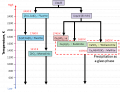
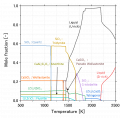
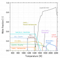
SA分析コードでは、一般に、α-Zr(O)とUO2の間のいわゆる「共晶」液状化モデルが実装されます。ただし、このモデルはSA分析用に指定された一種の簡略化されたモデルであるため、このモデルでは燃料棒の液化メカニズムを正確に説明できませんでした。基本的に、初期段階での燃料棒の液化の進行は、U-Zr-O三元状態図を使用して認識できます[8]。図2は、温度の上昇に伴う燃料棒の局所組成の変化を模式的に示しています。通常の操作では、平均組成はUO2-Zr線(通常はBWR燃料中のZrが豊富)の間のどこかにプロットされ、外面でのZrベース合金の酸化によってUO2-ZrO2線に向かって徐々にふるいにかけられます(A ⇒B⇒C⇒D)事故が進むにつれて。このモデルは、初期段階で燃料棒で起こっている化学反応が、UO2-ZrO2-Zr三元領域の相安定性に基づいて熱力学的に議論できることを示しています。この特定の地域では、蛍石(FCC)、面心正方晶(TET)、単斜晶、HCP、BCC、および液体の熱力学的データが必要です。 FCC、TET、および単斜晶相は本質的に酸化性固溶体であり、一方、HCPおよびBCC相は金属固溶体(合金)です。液相には、より複雑な熱力学的記述が必要です。比較的低温では、U-Zr-O溶融物が液体の主要な成分です(いわゆる「金属」溶融物)。金属溶融物の組成範囲は、温度の上昇とともに徐々に拡大しています。次に、高温(約2550°C以上)では、金属溶融物(U-Zr-O)と酸化溶融物(UO2-ZrO2)が互いに溶解する可能性があります。これには、U-Zr-Oシステムの液体の複雑な熱力学モデルが必要です。また、中間温度領域で形成される混和性ギャップには、より複雑な熱力学モデルが必要です。
亜化学量論のU-Zr-Oメルトが形成される。
燃料集合体部材の溶融
_Schematic_image_of_a_horizontal_cross_section_of_a_prototypic_BWR_Fuel_assembly._The_red_square_shows_the_section_illustrated_in_Fig._18(b)..png)
Figure 18(a) illustrates a horizontal cross section of a prototypic BWR fuel assembly, which is mainly consisted of fuel rod, control blade and channel box [9]. The fuel assembly is surrounded by a channel box made of Zr-base alloy. It should be noted in the case of BWR that the quantity of Zr is certainly larger than that of PWR (approximately twice in amount). Furthermore, an important feature is that the control blade is placed outside the channel box and away from the fuel rods.
Figure 18(b) indicates the schematic image of the liquefaction progression of the control blade and channel box. Major components for the interaction are (1) a control rod made of B4C absorber material and stainless steel (SS-304) cladding, (2) a blade sheath made of SS-316 and (3) a Zry-4 channel box. Several dominant reactions occur with increasing temperature:
(a) interaction between B4C and SS in a control blade,
(b) oxidation of the outer surface of the channel box,
(c) interaction between the B4C and SS melt and Zry-4 channel box,
(d) steam oxidation of B4C-SS-Zr melt and remaining B4C.
Consequently for the detailed understanding of the liquefaction progress of the BWR control blade and channel box, a comprehensive thermodynamic database for the Fe-Ni-Cr-Zr-B-C-O system is necessary. In the first step, reactions (a), (b), (c) and (d) could be evaluated based on several sub-systems.

Reaction (a) (B4C-SS system):
So-called ‘eutectic’ melting between B4C and SS could occur at approximately 1200 °C. The Fe-B-C ternary phase diagram indicates that the most of SS cladding (major component: Fe) and a small amount of B4C are liquefied by the ‘eutectic’ formation. Hence, a significant amount of B4C is able to remain in the B4C-SS melt [10]. For more detailed understanding of the ‘eutectic’ melting, one needs to evaluate selective Fe-C reactions as opposed Fe-B reactions in the Fe-B-C melt and the local precipitation of Cr-boride [11, 12]. Table 16 shows the current assessed status of the ternary sub-systems of the B4C-SS systems. (‘⭕’ means the full assessment and ‘-’ means that its system has not been assessed yet.) The most important sub-system for this particular interaction is clearly Fe-B-C, because Fe is a dominant component of SS, which is already stored in both of TAF-ID and NUCLEA. Also, Fe-Ni-Cr system is already stored in the both databases. By using these databases, the ‘simplified’ evaluation of the ‘eutectic’ melting between B4C and SS could be carried out. However, the databases are still insufficient for the other subsystems especially including Cr, B and C. Cr could selectively react with B and C during solidification of the melt. This reaction appears to be important for the characterization of metallic debris [13]. Table 16: Current assessed status of ternary sub-systems regarding the liquefaction of the BWR control rod, which stored in TAF-ID and NUCLEA
Reaction (b) (Zr-O system):
As for the thermodynamic understanding of the oxidation of the channel box, one needs the Zr-O binary database which is already stored in the both databases.
Reaction (c) (B4C-SS-Zr-O system):
After the control blade melt (SS-B4C melt) makes contact with the Zry channel box, there is an interaction between the SS-B4C melt and the partially oxidized Zr. Several chemical reactions could simultaneously progress and hence the overall phenomena are very complicated. A kinetic model is definitely necessary for the detailed understanding. Thermodynamic database could identify the tendency (driving force) or threshold condition for the reaction. The interaction’s progress depends on the thickness of the Zry surface oxide of the channel box. If the oxide film is not sufficiently protective in a non-oxidizing atmosphere, the interaction between SS-B4C melt and Zr can occur upon contact. As a result, B and C are transported to the Zry via liquid and could cause a sudden change of the system toward its equilibrium state, in which Zr-boride or Zr-carbide could precipitate in the melt. This is predicted to be an exothermic reaction. Table 17 shows the ternary subsystems regarding the liquefaction between the non-oxidized Zircaloy channel box and the SS-B4C melt (in addition to Table 16). The dominant subsystem for this particular interaction could be Fe-Zr-X (X: Ni,Cr,B,C). The database is still insufficient for developing the mechanistic model. Also, considering the solidification path of the metallic debris, one needs to improve Zr-B-X and Zr-C-X databases.
Table 17: Current assessed status of ternary subsystems regarding the interaction between SS-B4C and non-oxidizing Zr (in addition to Table 16) On the other hand, in the case of a thick oxide film on the Zry channel box. This interaction (SS-B4C and Zr) does not significantly occur and only SS-B4C melt relocates to the lower part (the channel box could maintain its original configuration during the absorber rod melting). Then, after melting of the Zr-channel box interior at higher temperatures, one needs to evaluate the dissolution of ZrO2 in the metallic melt which could be extremely important to the metallic debris characteristics. Table 18 shows the ternary sub-systems with oxygen. Both databases can roughly evaluate the effects of oxidation. However, the formation of ternary compounds could not be sufficiently evaluated using these databases. Also, TAF-ID does not store any databases on the stable compounds of B-oxide in the melt. Reaction (d) (B4C-SS-Zr-O system): The steam oxidation of the SS-B4C-Zr melt is extremely important for the characteristics of the metallic debris. Also, the formation of B2O3 could accelerate the liquefaction of the fuel rod, because the melting temperature range of B2O3 is ~ 450-465 °C and it could allow the easy contact/wetting with the fuel rod. Moreover, volatilization of B is extremely accelerated by the steam oxidation and gaseous boron oxides could influence the chemical stability of volatile FP, such as Cs and I [10, 14-15]. The improvement of B-related database is highly recommended.
On the other hand, in the case of a thick oxide film on the Zry channel box. This interaction (SS-B4C and Zr) does not significantly occur and only SS-B4C melt relocates to the lower part (the channel box could maintain its original configuration during the absorber rod melting). Then, after melting of the Zr-channel box interior at higher temperatures, one needs to evaluate the dissolution of ZrO2 in the metallic melt which could be extremely important to the metallic debris characteristics.
Table 18 shows the ternary sub-systems with oxygen. Both databases can roughly evaluate the effects of oxidation. However, the formation of ternary compounds could not be sufficiently evaluated using these databases. Also, TAF-ID does not store any databases on the stable compounds of B-oxide in the melt.
Reaction (d) (B4C-SS-Zr-O system):
The steam oxidation of the SS-B4C-Zr melt is extremely important for the characteristics of the metallic debris. Also, the formation of B2O3 could accelerate the liquefaction of the fuel rod, because the melting temperature range of B2O3 is ~ 450-465 °C and it could allow the easy contact/wetting with the fuel rod. Moreover, volatilization of B is extremely accelerated by the steam oxidation and gaseous boron oxides could influence the chemical stability of volatile FP, such as Cs and I [10, 14-15]. The improvement of B-related database is highly recommended.
b. Transient and late phases
_in_the_transient_and_late_phases_of_in-vessel_phenomena.png)
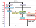
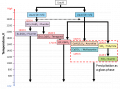
Figures 4 (b1)-(b5) indicate the schematic image of the prototypic five stages for the transient and late phases:
(b1) Start significant relocation of the fuel melt,
(b2) Blockage of steam flow at lower part of the core by the relocated debris,
(b3) Formation of corium pool,
(b4) Secondary relocation of corium melt to the lower plenum,
(b5) Liquefaction and stratification of oxidic and metallic melt in the lower plenum.
(b1) Start significant relocation of the fuel melt:
The leading relocation mainly of the metal components (such as the control rod blades and channel box) begins and then the partial blockage of the coolant flow path occurs by the relocated melt. After that, the relocation to the lower head of the U-Zr-O melt occurs. It is not sufficient to understand precisely these complicated reactions only by the thermodynamic approach because each reaction is accompanied by the rapid temperature changes. However, the reaction trends according to the accident scenarios could be evaluated by the thermodynamic databases. In the FDNPS accident, the different progression from the typical accident scenarios could occur (see chapter 4.6). The improvement/enlargement of the thermodynamic databases is expected to show some of the reasons of these deviations. Especially, it is important to improve the accuracy of the high temperature database of U-Zr-O system because the initial U-Zr-O melt is generally oxidized but the composition of the melt becomes more complex during the relocation stage.
(b2) Blockage of steam flow at lower part of the core by the relocated debris:
The blockage of the lower part of the core occurs by the collapsed oxide and metal debris. However, the BWR drainage scenario could occur in case of the insufficient blockage [16]. It is necessary to enhance accuracy of the U-Zr-Fe-O system data because the degree of blockage depends on the degree of oxidation of debris and the dissolution of the oxidized structural materials by the oxidic melt. As shown in chapter 4.5, the reaction between the U-Zr-O melt and Fe-oxide could proceed rapidly with local heat generation according to the thermodynamic analysis. This process could enhance the drainage scenario.
(b3) Formation of corium pool:
The melted and collapsed fuel is once cooled and re-solidified by the inhibition of the steam oxidation of Zr. After that, the temperature rises again by the decay heat, and this leads to the corium pool formation with a crust. The main components of corium are UO2-ZrO2 due to the oxidation progression of Zr. (However, in the case of the unit-2 of FDNPS, in which fuel melt could progress under the steam-served condition, the phase separation of oxidic and metallic melts could occur.) Therefore, the important system in this stage is also the U-Zr-O system.
(b4) Secondary relocation of corium melt to the lower plenum:
The corium pool is insulated by the surrounding crust layer and then it gradually expands. When the crust cannot support the corium weight with the corium extenuation, then the liquid corium can have secondary relocations to the lower plenum in a short period, either as rivulets or larger masses. The important database for this particular stage is U-Zr-Fe-O. However, the Fe-related databases are insufficient. The improvement is necessary. Besides, if the blockage by the crust layer is incomplete, it could lead to, not the corium pool growth, but the drainage scenario [16].
(b5) liquefaction and stratification of oxidic and metallic melt in the lower plenum:
In a typical accident scenario, the debris, which has fallen into the lower plenum and has cooled and solidified again on the lower plenum. Subsequent reheating and melting, could cause a stratification of the oxide and metal layers. In this scenario, the oxide melt is composed mainly of UO2-ZrO2-FeO, and mixed with the easily oxidized FP and presumably boron oxide. Metallic melts are mainly composed of SS-Zr-U, and mixed with metallic FP and B compounds. In some cases, the metal layer might be separated into heavy metal (U-Zr-rich) and light metal (Fe-rich) layers, according to MASCA results [17].
In such a multi-component system, it is difficult to evaluate its properties only by experiments, and conversely, it is effective to roughly evaluate the chemical state by the thermodynamic database [18]. Therefore, the accumulation of the experimental data and the improvement of thermodynamic databases and their joint evaluation for the multi-component system is continuously necessary.
Consequently, the base thermodynamic system for investigating these sequential reactions is U-Zr-SS-B4C-O. By considering the metallic corium and the oxidic corium separately, metallic corium can be evaluated by mainly Fe-Zr-X (X means U, Cr, Ni, B or C), and basically, it is important to enlarge the thermodynamic data already shown in the early phase section. On the other hand, the oxidic corium consists of mainly U-O-X and Zr-O-X (X means Fe, Cr, Ni, B or C). Table 19 shows the currently assessed status of U-O-X (see Table 18 as for the Zr-O-Fe system). The important systems are U-O-Zr, U-O-Fe and Zr-O-Fe. In the future, the enlargement of the U-Zr-Fe-O system will be an important issue for performing FDNPS debris analysis.
In-vessel debrisの凝固
In-vessel debrisの凝固説明文追記
二酸化物コリウムの凝固とU-Zr-Oの凝固が異なることの説明
In-Vessel debrisの凝固に関する熱力学解析 (凝固パス逆問題解析)
U-Zr-O系デブリの凝固パス解析1)亜量論U-Zr-Oメルトからの凝固
図5に
最高到達温度 約1900℃~約2550℃ 説明文追記 〇〇組成の液相が 急冷:〇相と〇相が検出される可能性 徐冷:〇相と〇相が検出される可能性
Case-2:UO2-ZrO2コリウムからの凝固
最高到達温度 約2550℃~ 説明文追記 〇〇組成の液相が 急冷:〇相と〇相が検出される可能性 徐冷:〇相と〇相が検出される可能性
- Example.jpg
キャプション1
- Example.jpg
キャプション2
Case-3:金属メルトからの凝固(現在解析中)
3-1) SS-B4C 最高到達 〇〇組成の液相が 急冷:〇相と〇相が検出される可能性 徐冷:〇相と〇相が検出される可能性
3-2) SS-B4C-Zr 〇〇組成の液相が 急冷:〇相と〇相が検出される可能性 徐冷:〇相と〇相が検出される可能性
- 凝固パス逆問題解析
実デブリサンプル中に同定された相により、デブリ最高到達温度、冷却状態(徐冷、急冷)および組成を評価することができる。 参考リンク
Ex-vesselでのdebris溶融・凝固
事故時においてRPV下部プレナムにスランピングした燃料デブリが再溶融し、下部ヘッドを破損させた場合、RPVからペデスタルへ燃料デブリが移行する。1Fのペデスタル部では玄武岩系(シリカ系)コンクリートが使用されており、落下した溶融燃料とコンクリートの高温反応(Molten Core Concreate Interaction; MCCI)を起こすと想定されている。MCCIの進行に影響する因子としては、コンクリートの材質、移行してきた燃料デブリの組成(特に、平均的な酸化度や金属成分が含まれるかどうか)、デブリ温度(比較的温度の低いデブリが崩落する場合には、MCCIが進行しない可能性が考えられる(内部調査結果:2号機、3号機)リンク、3号機まだ)、また、デブリの特性には、冷却条件(徐冷or急冷)も影響する。
Ex-vessel debrisの凝固 に関する 熱力学解析
シリカ系コンクリートと溶融コリウムの間でMCCIが発生したと仮定し、熱力学計算ソフトThermo-calcを使用し、Ex-vessel debris凝固時の析出相の同定と成分偏析の解析を実施した。データベースはOECD/NEAの国際汎用熱力学データベースTAF-ID[5]を使用した。
シリカ系コンクリート、PWR条件でのコリウムのケース(CEA 模擬試験条件)
仏国CEAで行われた、シリカ系コンクリートとPWR条件を想定した模擬コリウムを用いたEx-vessel debrisの凝固試験[6]を参考に、凝固時の相析出挙動(凝固パス)の解析を実施した[7]。 本項目の論文は現在執筆中、参考文献
| Corium 1 | Corium 2 | |
|---|---|---|
| Al | 1.2 | 1.0 |
| Ca | 18.8 | 4.8 |
| Si | 13.3 | 26.3 |
| U | 3.7 | 1.4 |
| Zr | 2.8 | 1.6 |
| O | 60.2 | 64.9 |
- CEA試験概要
- - 試験条件
- CEA試験の模擬コリウム組成(表X1)
- 模擬燃料デブリ(PWR条件):UO2-ZrO2の混合酸化物
- コンクリート:SiO2-Al2O3-CaOの混合物。Corium1:石灰岩(Caリッチ)コンクリート。Corium2:シリカ系(Siリッチ)コンクリート。
- 最高到達温度:2500℃
- CEA試験の模擬コリウム組成(表X1)
- - 試験結果
- Caリッチデブリ:Corium1(図X2、表X2)
- 母相:Ca、Siガラス(黒色)
- 析出相1:(U,Zr,Ca)O2のデンドライト(白色)
- 析出相2:珪酸塩化合物(灰色)
- Caリッチデブリ:Corium1(図X2、表X2)
- Siリッチデブリ:Corium2(図X3、表X3)
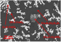
- 試験では、コリウムが2層に成層化した。それぞれの領域において、母相と析出相が逆になっていることが観察されている。EDS分析では模擬デブリが脆く測定が困難であったため、領域1のみが分析された。
- 領域1
- 母 相:(U,Zr,Ca)O2(白色)
- 析出相1:SiO2の球状晶(黒色)
- 析出相2:Si化合物(灰色)
- 領域2(組織観察結果のみ)
- 母相:おそらくSiガラス相(黒色)
- 析出相1:おそらくU,Zr酸化物(白色)
- 析出相2:おそらくSi化合物(灰色)
- Siリッチデブリ:Corium2(図X3、表X3)
図X2:BSE像(Corium11:Caリッチ)[6]
- EDS result C1 1.png
表X2:EDS分析結果(Corium1:Caリッチ)[6]
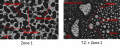
図X3:BSE像(Corium2:Siリッチ)[6]

表X3:EDS分析結果(Corium2:Siリッチ)[6]

- 熱力学解析による凝固パス概要
- Caリッチデブリ:Corium1(図X4、X5)
- U,Zr酸化物(一部Caが固溶):(Zr,U,Ca)O2が析出(約2160℃) → Uリッチ or Zrリッチの酸化物に相分離(約1470℃以下)
- 珪酸塩(ジルコン):Ca2SiO4が析出(約1470℃)
- コンクリート成分化合物:Si化合物orガラスが析出
- まずU,Zr酸化物がデンドライトとして析出し、続いて1450℃程度で珪酸塩が析出、残存液相部がガラスとして母相になったと考えると試験結果と整合する。
- Siリッチデブリ:Corium2(図X6、X7)
- 高温で液相が2相に分離:Uリッチ液相+Zrリッチ液相
- Uリッチ液相
- Siガラス相:SiO2単体が析出(約1450℃)
- U,Zr酸化物:(U,Zr)O2が析出(約1380℃)
- Si化合物(珪酸塩)析出
- Zrリッチ液相
- Zr酸化物(一部U,Caが固溶):(Zr,U,Ca)O2が析出(約1930℃) → ジルコン:ZrSiO4が析出(1590℃)、Uが分離
- 残存液相部がUリッチ液相と同様の析出挙動:Si化合物orコンクリート成分ガラス(Al,Ca,Si)が析出
- 解析結果では、高温で液相が2相分離する結果となった。Uリッチ液相はまずSiO2が析出し、その後にU,Zr酸化物+Si化合物が墓相として析出。一方で、Zrリッチ液相ではまずZr酸化物が析出し、Si化合物、母相としてガラスが析出すると予測される。分離した各液相で凝固パス(析出相と母相の順番)が逆になっており、それぞれ試験結果の2層領域に対応していると考えられる。つまり、試験においても溶融時に液相で2相分離を起こしたと考えられ、密度の重いUリッチ液相が下部に(領域1)、Zrリッチ液相が上部(領域2)に成層化し凝固したと考えられる。また、解析結果と試験結果において各領域での相状態(析出相と母相)の整合性が確認できる。
図X4:試験条件1(Caリッチ)の解析結果
図X5:試験条件1(Caリッチ)の凝固パス概略図
図X6:試験条件2(Siリッチ)の解析結果
図X7:試験条件2(Caリッチ)の凝固パス概略図


BWR条件でのコリウムの解析(1F条件)
| wt% | |
|---|---|
| UO2 | 78.4 |
| ZrO2 | 21.6 |
1F事故で予測されるコリウム組成において、凝固時の相析出挙動(凝固パス)の解析を実施した。
- コリウム組成
- 模擬燃料コリウム(表X4):UO2-ZrO2の混合酸化物(重量比約 4:1)
- コンクリート(表X5):SiO2-Al2O3-CaOの混合物(重量比約 20:5:4) = Siリッチコンクリート
| wt% | |
|---|---|
| Al2O3 | 17.0 |
| CaO | 14.1 |
| SiO2 | 68.9 |
- 解析結果(コンクリート:燃料コリウム=5:5)
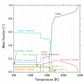
- 解析結果による凝固パス概要(図X8,9)
- 高温で液相が2相に分離:Zrリッチ液相+Siリッチ液相
- Zrリッチ液相 → U,Zr酸化物(一部Caが固溶) (約1960℃)
- Siリッチ液相 → Si化合物(ジルコン等珪酸塩) (約1430℃以下)
- コンクリート成分ガラス(Al,Ca,Si) (母相)
- 1F条件では、高温では液相が2相に分離:Zrリッチ+Siリッチする計算結果となった。Zrリッチ液相は、約2000℃程でZr酸化物(U固溶)で凝固し、さらに温度が下がるとジルコン+U,Zr酸化物に分離、という凝固パスを経る。この際、ジルコンが多く(U,Zr酸化物と同量以上に)析出すると考えられる。一方で、Siリッチ液相では、比較的低温まで液相状態が維持され、約1350℃以下からSiO2及びSi化合物が析出 or ガラスとして析出して母相となると考えられる。
図X8:1F組成コリウム(コンクリート5:燃料コリウム5)
図X9:1F組成コリウム凝固パス(コンクリート5:燃料コリウム5)


既往知見
模擬試験
過去の模擬試験を参照。(追記予定)
フランス・CEAでは、大型のMCCI試験装置(VULCANO: Versatile UO2 Lab for Corium ANalysis and Observation)を用いてMCCIに伴うコンクリートの浸食挙動が調べられてきた。これとともに、試験で生成したMCCI生成物の性状等が調べられている。
この試験シリーズのひとつである「VBS-U4試験」では、UO2/ZrO2比やコンクリート組成等が1F1号機の想定に比較的近い条件であり、溶融させたUO2-ZrO2-SiO2酸化物と溶融させたステンレス鋼を、シリカ質コンクリートに流し込むことでMCCIを引き起こしている。組織観察の結果、溶融プール層:(U,Zr)O2-x; (Zr,U)O2-x; 結晶質シリカ;珪酸ガラス、金属層:未酸化のステンレス(Fe-Ce-Ni)、が形成された。また、デブリとコンクリートとの境界付近において、高Uジルコン(Zr,U)SiO4の形成も確認された。[8]
また、コンクリートの浸食自体は少ないものの、底部注水による急冷条件のもと「VW-U1試験」が実施された。この試験では、底部にポーラス状コンクリートを配置し、MCCI開始後にポーラス状コンクリートへの注水によりデブリの急冷を行っている。組織観察の結果、サンプルの採取箇所によらずデブリの微細構造はおおよそ共通しており、Siリッチなマトリックス中にUリッチな(U,Zr)O2やZrリッチな(Zr,U)O2が析出する構造であった。上述のVBS-U4試験で生成した結晶質シリカや高Uジルコンの形成は認められず、急冷とそれに伴うコンクリート浸食の抑制がこれらの相の形成に影響したものと推定された。[9]
2017年度には、1Fで想定される材料組成やコンクリート浸食程度などを考慮した大型MCCI試験である「VF-U1試験」が行われた。組織観察の結果、炉心材料(UO2, Zr, ZrO2, ステンレス鋼)がコンクリートと反応した後の溶融プール部は,コンクリート由来のSi, Ca, Alや燃料由来のU, Zrを多く含む酸化物相と,ステンレス鋼由来のFeを多く含む金属相に分かれることが分かった。各相の特徴は以下の通り。[10][11]
- 酸化物相は,Si, Ca, Al濃度の高いマトリックス中に,U-Zr酸化物の粒子やFe-Cr酸化物の粒子が析出する構造をとり,同様の構造が溶融プール内に広くみられる。
- 金属相は,主にFe-Ni系の合金で,Cr濃度は初期の材料として投入したステンレス鋼のCr濃度よりも低い。主に,溶融プールの底部(コンクリートとの境界部)に塊として存在。
実際の1Fにおいては落下してきたデブリ性状や冷却条件によるが、上記模擬試験のように成層化、相分離が発生している可能性がある。
チェルノブイリLava
チェルノブイリ原子力発電所事故を参照。
チェルノブイリ原子力発電所事故で発生したデブリは、溶融した燃料が蛇紋岩コンクリートと反応したものであり、主に褐色デブリ(Brown lava)と黒色デブリ(Black lava)の2種類が発見されている。双方ともにメインマトリクスは珪酸塩ガラスであり、その組成もほぼ同様である。一方で、ガラス相以外の析出物においては褐色デブリの方がU濃度が高くなっている。チェルノブイリでのデブリ生成条件は1Fと異なるが、これらのデブリはMCCIが長時間継続され形成されたものであり、1Fにおいてもペデスタルに移行したデブリが徐冷されていた場合には、複数の性状のデブリが形成・成層化している可能性がある。


Ex-vessel debrisの予測される特徴
- コンクリート成分が混入することで、固相と液相が共存する温度域(液相線温度:全て溶融 ⇔ 固相線温度:全て凝固)の温度差が約700-800℃に拡大する。固相と液相の比重差により、泥水のような状態になり、層分離が起こる可能性がある。チェルノブイリのデブリ:Brawn/Black LAVA
- 高温で液相が2相に分離(U,Zリッチ ⇔ Siリッチ)し、これら液相間の比重差により層分離する可能性がある。この場合、各層では凝固パス(析出相、母相)が逆転するなど異なると考えられる。CEA模擬試験
- 主要構成組織は以下の3つに区別できる。
- - U,Zr酸化物:(U,Zr)O2 Fluorite, Tetragonal
- - Si化合物:(Zr,U)SiO4
- - コンクリートガラス:SiO2 + Al,Ca成分
- ペデスタルへ移行してきた燃料デブリ中に金属成分が含まれる場合、デブリ下部に密度の高い金属層が形成される可能性がある。
関連項目
参考文献
- ↑ 1.0 1.1 原子力安全協会(H10?),"軽水炉燃料のふるまい"
- ↑ P. Hofmann, D.K. Peck, "UO2/Zircaloy-4 chemical interactions from 1000 to 1700゚C under isothermal and transient temperature conditions", J. Nucl. Mat. 124, 80-105 (1984). https://doi.org/10.1016/0022-3115(84)90013-8
- ↑ 3.0 3.1 3.2 M.H.A. Piro, Advances in Nuclear Fuel Chemistry, Woodhead Publishing, 555-625, ISBN 9780081025710 (20202).
- ↑ B. Clément, N.H. Girault, G. Repetto, D. Jacquemain, A.V. Jones, M.P. Kissane, P. von der Hardt, "LWR severe accident simulation: synthesis of the results and interpretation of the first Phebus FP experiment FPT0", Nucl. Eng. Des. 226, 5-82 (2003). https://doi.org/10.1016/S0029-5493(03)00157-2
- ↑ Thermodynamics of Advanced Fuels – International Database, OECD/NEA : https://www.oecd-nea.org/science/taf-id/
- ↑ 6.0 6.1 6.2 6.3 6.4 6.5 A. Quaini, C. Journeau, S. Gosse, T. Alpettaz, E. Brackx, R. Domenger, A. Chocard, F. Hodaj, "Experimental contribution to the corium thermodynamic modelling – the U-Zr-Al-Ca-Si-O system", Annals of Nuclear Energy, 93, 43-49 (2016). http://dx.doi.org/10.1016/j.anucene.2016.01.043
- ↑ T. Sato et al. (2020), to be submitted
- ↑ 8.0 8.1 8.2 T. Kitagaki, H. Ikeuchi, K. Yano, J.H. Haquet, L. Brissonneau, B. Tormos, P. Piluso and T. Washiya, "Characterization of the VULCANO test products for fuel debris removal from the Fukushima Daiichi Nuclear Power Plant", Prog. Nucl. Sci. and tech. 5, 217-220 (2018). http://dx.doi.org/10.15669/pnst.5.217
- ↑ T. Kitagaki, H. Ikeuchi, K. Yano, L. Brissonneau, B. Tormos, R. Domenger, J. Roger and T. Washiya, "Effect of quenching on molten core-concrete interaction product", J. Nucl. Sci. Technol. 56, 904-914 (2019). https://doi.org/10.1080/00223131.2019.1604272
- ↑ A. Nakayoshi, H. Ikeuchi, T. Kitagaki, T. Washiya, V. Bouyer, C. Journeau, P. Piluso, E. Excoffier, C. David, V. Testud, "Knowledge obtained from dismantling of large-scale MCCI Experiment products for decommissioning of Fukushima daiichi nuclear power station", Proc. of International Topical Workshop on Fukushima Decommissioning Research, Naraha, Fukushima, Japan, 24-26, May, 2019.
- ↑ L. Brissonneau, H. Ikeuchi, P. Piluso, J. Gousseau, C. David, V. Testud, V. Bouyer, T. Kitagaki, A. Nakayoshi, S. Dubois, T. Washiya, "Material characterization of the VULCANO corium concrete interaction test with concrete representative of Fukushima Daiichi Nuclear Plants.", J. Nucl. Mater. 528, 151860 (2020). https://doi.org/10.1016/j.jnucmat.2019.151860
- ↑ 12.0 12.1 B.E. Burakov, "Material study of Chernobyl “lava” and “hot” particles”, International Experts", Meeting on Decommissioning and Remediation after a Nuclear Accident Vienna, Austria (2013). http://www-pub.iaea.org/iaeameetings/IEM4/30Jan/Burakov.pdf
事故進展の推定
号機毎の事故進展
関連研究
以下の表は、福島第一原子力発電所の廃炉及び原子力発電の安全性向上に資する観点で、既存及び進行中の研究をまとめたものである。
| 事故進展過程 | |||||
|---|---|---|---|---|---|
| 関連事象 | 〜炉心損傷 | 〜下部プレナム移行 | 〜RPV破損 | 〜水素爆発 | 水素爆発以降 |
| 熱水力(RPV内) | |||||
| 熱水力(RPV外) | |||||
| 炉心物質溶融挙動(炉心部) | XR-2試験
CMMR試験 CLADS-MADE試験 |
||||
| 炉心物質溶融挙動(炉心部以外) | LIVE試験 | ||||
| FP放出 | |||||
| RPV破損 | H30•1F推進費[* 1] | ||||
| MCCI | |||||
| 未解明問題 | |||||
| 備考 |
| ||||
燃料デブリの性状把握PJにおける既往研究(報告書)
※リンク先はGr1